
Page 39 - Hydrocarbon
P. 39
26 Exploration Methods and Techniques
amplitude of anomaly distance along profile line OR? amplitude of anomaly distance along profile line
LPG
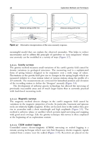
Figure 3.7 Alternative interpretations of the same anomaly response.
meaningful model that can explain the observed anomalies. This helps to reduce
uncertainties and to address the principle of equivalence or ‘non-uniqueness’ where
one anomaly can be modelled in a variety of ways (Figure 3.7).
3.2.1.1. Gravity surveys
The gravity method measures small variations of the earth’s gravity field caused by
density variations in geological structures. The measuring tool is a sophisticated
form of spring balance designed to be responsive over a wide range of values.
Fluctuations in the gravity field give rise to changes in the spring length which are
measured (relative to a base station value) at various stations along the profile of a
2D network. The measurements are corrected for latitudinal position and elevation
of the recording station to define the ‘Bouguer’ anomaly (Figure 3.8).
The development of airborne gravity technology has allowed the surveying of
previously inaccessible areas and of much larger basins than is currently practical
with land-based measuring tools.
3.2.1.2. Magnetic surveys
The magnetic method detects changes in the earth’s magnetic field caused by
variations in the magnetic properties of rocks. In particular, basement and igneous
rocks are relatively highly magnetic. If they are located close to the surface they give
rise to anomalies with a short wavelength and high amplitude (Figure 3.9). The
method is airborne (plane or satellite) which permits rapid surveying and mapping
with good areal coverage. Like the gravity technique this survey is often employed
at the beginning of an exploration venture.
3.2.1.3. CSEM seabed logging
Controlled source electro-magnetic (CSEM) surveying or seabed logging is a
remote sensing technique which uses very low frequency electro-magnetic signals
emitted from a source near the seabed (Figure 3.10). Receivers are placed on the