
Page 43 - Hydrocarbon
P. 43
30 Exploration Methods and Techniques
reflectivity series
or reflective
rock source seismic
units AI log coefficient log wavelet trace
depth time *
*
convolution
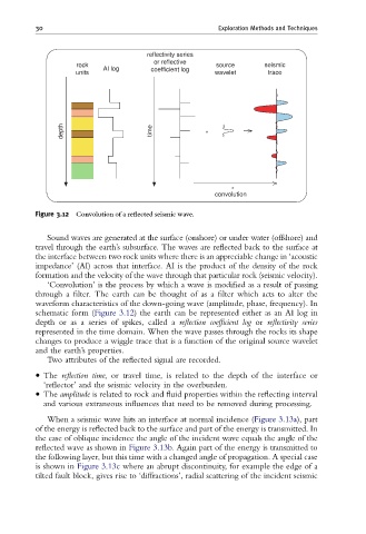
Figure 3.12 Convolution of a re£ected seismic wave.
Sound waves are generated at the surface (onshore) or under water (offshore) and
travel through the earth’s subsurface. The waves are reflected back to the surface at
the interface between two rock units where there is an appreciable change in ‘acoustic
impedance’ (AI) across that interface. AI is the product of the density of the rock
formation and the velocity of the wave through that particular rock (seismic velocity).
‘Convolution’ is the process by which a wave is modified as a result of passing
through a filter. The earth can be thought of as a filter which acts to alter the
waveform characteristics of the down-going wave (amplitude, phase, frequency). In
schematic form (Figure 3.12) the earth can be represented either as an AI log in
depth or as a series of spikes, called a reflection coefficient log or reflectivity series
represented in the time domain. When the wave passes through the rocks its shape
changes to produce a wiggle trace that is a function of the original source wavelet
and the earth’s properties.
Two attributes of the reflected signal are recorded.
The reflection time, or travel time, is related to the depth of the interface or
‘reflector’ and the seismic velocity in the overburden.
The amplitude is related to rock and fluid properties within the reflecting interval
and various extraneous influences that need to be removed during processing.
When a seismic wave hits an interface at normal incidence (Figure 3.13a), part
of the energy is reflected back to the surface and part of the energy is transmitted. In
the case of oblique incidence the angle of the incident wave equals the angle of the
reflected wave as shown in Figure 3.13b. Again part of the energy is transmitted to
the following layer, but this time with a changed angle of propagation. A special case
is shown in Figure 3.13c where an abrupt discontinuity, for example the edge of a
tilted fault block, gives rise to ‘diffractions’, radial scattering of the incident seismic