
Page 254 - Hydrocarbon Exploration and Production Second Edition
P. 254
Well Dynamic Behaviour 241
cased hole DST may be considered. Only the interval of interest is perforated and
allowed to flow. All other intervals remain isolated behind casing. Each interval is
sealed off prior to testing another. In both types of DST it is possible to run a
downhole pressure gauge, and therefore to perform a drawdown and build-up survey.
10.5. Tubing Performance
The previous sections have considered the flow of fluid into the wellbore. This
is commonly referred to as the ‘inflow performance’. The PI indicates that as the
flowing wellbore pressure (P wf ) reduces, so the drawdown increases and the rate of
fluid flow to the well increases. Recall for an oil well (Figure 10.13)
Drawdown pressure DP DD ¼ P P wf ðpsiÞ or ðbarÞ
Q
3
Productivity index PIðÞ ¼ ðbbl=d=psiÞ or ðm =d=barÞ
DP DD
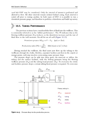
Having reached the wellbore, the fluid must now flow up the tubing to the
wellhead, through the choke, flowline, separator facilities and then to the export or
storage point; each step involves overcoming some pressure drop.
The pressure drops can be split into three parts; the reservoir or inflow, the
tubing and the surface facilities, with the linking pressures being the flowing
wellbore pressure (P wf ) and the tubing head pressure (P th ). To overcome the choke
and facilities pressure drops a certain tubing head pressure is required. To overcome
ΔP ch ΔP facs
stock
P sep
P th tank
flowline 1 atm
Pressu redrop in :
ΔP tbg
ΔP DD reservoir
ΔP tbg tubing
ΔP ch choke
reservoir P
P wf ΔP facs facilities
ΔP DD
Figure 10.13 Pressure drops in the production process.