
Page 270 - Hydrocarbon Exploration and Production Second Edition
P. 270
Well Dynamic Behaviour 257
number of pump stages. At additional cost, a variable speed drive can be installed to
allow the motor speed, and thus the flow rate, to be changed.
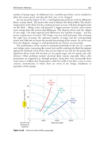
As can seen from Figure 10.28, a centrifugal pump performs work by lifting the
fluid a certain ‘head’. The head is the vertical distance the fluid is lifted. The head is
independent of the fluid, but the resulting pressure increase will depend significantly
on the fluid – lifting water will generate a bigger pressure increase (and require
more energy from the motor) than lifting gas. The diagram shows only the output
of one stage. The total required head determines the number of stages – and the
power requirement of motor. ESP design concerns itself primarily with choosing
the right type of pump, the optimum number of stages and the corresponding
motor and cable size to ensure the smooth functioning of the system. As can be seen
from the diagram, changes in well productivity are hard to accommodate.
The performance of the system is monitored primarily by the use of a current
and voltage meter, measuring the motor load and by analysing the fluid throughput
against the hydraulic head. If the rates are too high or too low for the pump, then
significant thrust loads will develop on the pump stages and the pump may self-
destruct. Other problems include electrical short circuits especially when cable
penetrators are required (e.g. through packers). Runs lives vary enormously from
many years in shallow, low temperature, solids free wells to less than a year in more
extreme environments or where there are errors in the design, installation or
operation of the pumps.
min.
operating
range
60
best
efficiency
per stage (ft) 40 line
max.
operating
head 60 Hz 70 Hz range
50 Hz
20
40 Hz
0
0 4000 8000 12000
convert from liquid rate (bpd)
pressure to
head first
Figure 10.28 Electrical submersible pump stage.