Page 44 - Hydrogeology Principles and Practice
P. 44

HYDC02  12/5/05  5:37 PM  Page 27


                                                                                 Physical hydrogeology  27


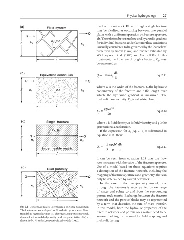
                                                               the fracture network. Flow through a single fracture
                                                               may be idealized as occurring between two parallel
                                                               plates with a uniform separation or fracture aperture,
                                                               2b. The relation between flow and hydraulic gradient
                                                               for individual fractures under laminar flow conditions
                                                               is usually considered to be governed by the ‘cubic law’
                                                               presented by Snow (1969) and further validated by
                                                               Witherspoon et al. (1980) and Gale (1982). In this
                                                               treatment, the flow rate through a fracture, Q , may
                                                                                                   f
                                                               be expressed as:

                                                                          dh
                                                               Q =−2bwK                           eq. 2.11
                                                                 f      f
                                                                             dl
                                                               where w is the width of the fracture, K the hydraulic
                                                                                             f
                                                               conductivity of the fracture and  l the length over
                                                               which the hydraulic gradient is measured. The
                                                               hydraulic conductivity, K , is calculated from:
                                                                                   f
                                                                    ρ 2b  2
                                                                     g()
                                                               K =                                eq. 2.12
                                                                 f     µ
                                                                     12
                                                               where ρ is fluid density, µ is fluid viscosity and g is the
                                                               gravitational acceleration.
                                                                 If the expression for K (eq. 2.12) is substituted in
                                                                                   f
                                                               equation 2.11, then:

                                                                           3
                                                               Q =−  2  wg ρ bd h                 eq. 2.13

                                                                 f      µ
                                                                     3       l d
                                                               It can be seen from equation 2.13 that the flow
                                                               rate increases with the cube of the fracture aperture.
                                                               Use of a model based on these equations requires
                                                               a description of the fracture network, including the
                                                               mapping of fracture apertures and geometry, that can
                                                               only be determined by careful fieldwork.
                                                                 In the case of the dual-porosity model, flow
                                                               through the fractures is accompanied by exchange
                                                               of water and solute to and from the surrounding
                                                               porous rock matrix. Exchange between the fracture
                                                               network and the porous blocks may be represented
                                                               by a term that describes the rate of mass transfer.
                   Fig. 2.8 Conceptual models to represent a fractured rock system.
                                                               In this model, both the hydraulic properties of the
                   The fracture network of aperture 2b and with groundwater flow
                                                               fracture network and porous rock matrix need to be
                   from left to right is shown in (a). The equivalent porous material,
                                                               assessed, adding to the need for field mapping and
                   discrete fracture and dual porosity models representative of (a) are
                   shown in (b), (c) and (d), respectively. After Gale (1982).  hydraulic testing.
   39   40   41   42   43   44   45   46   47   48   49