
Page 169 - Improving Machinery Reliability
P. 169
Machinery Reliability Audits and Reviews 141
ence of any manufacturer under close consideration. Examination of a manufactur-
er’s experience should serve to identify design extrapolations, or scale-ups. In exam-
ining manufacturers’ experience, the purchaser’s engineer cannot, in many cases,
look at data such as maximum horsepower compressor built to date. The following
example will illustrate this point.
Let us assume a machine has been furnished with 10 equally loaded cylinders
absorbing a total of 14,000 HP. The manufacturer may proudly point to his 14,000
HP experience when bidding, say, an %cylinder machine absorbing “only” 13,000
PIP. He is not likely to emphasize that his 13,000 HP machine may subject many of
the Compressor components to forces that are approximately 16% higher than those
seen by his well-proven 14,000 HP machine.
The value of component strength comparisons between competing offers is also
evident from a review of manufacturers’ frame-rating terminology. How does one
compare one vendor’s “instantaneous overload capacity” with another vendor’s
“continuous overload capacity,” “rated capacity,” or “design capacity?’ Component
strength analysis is one way to obtain a grasp of design conservatism and, thus, ven-
der standing. This analysis should include the load-carrying capability of the various
compressor bearings, cylinder design factors of safety, and combined gas and inertia
loading of compressor components.
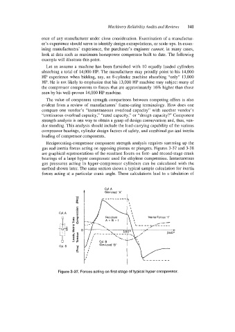
Reciprocating-compressor component strength analysis requires summing up the
gas and inertia forces acting on opposing pistons or plungers. Figures 3-37 and 3-38
are graphical representations of the resultant forces on first- and second-stage crank
bearings of a large hyper compressor used for ethylene compression. Instantaneous
gas pressures acting in hyper-compressor cylinders can be calculated with the
method shown later. The same section shows a typical sample calculation for inertia
forces acting at a particular crank angle. These calculations lead to a tabulation of
CYl. A
A Gas Load “A
lnerlia Forces “)1.
360’
I
Figure 3-37. Forces acting on first stage of typical hyper compressor.