
Page 173 - Improving Machinery Reliability
P. 173
Machinery Reliability Audits and Reviews 145
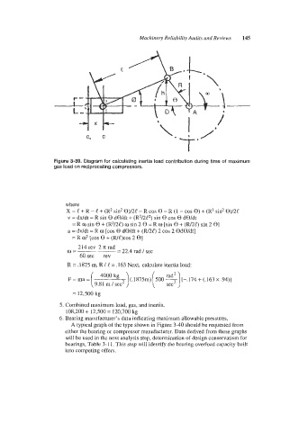
Figure 3-39. Diagram for calculating inertia load contribution during time of maximum
gas load on reciprocating compressors.
where
x = e + R - k‘ + (R~ sin2 @)ne - R cos 0 = R (1 - cos 0) + (R~ sin2 9)/2C
v = dx/dt = R sin 0 d0/dt + (R2/2t2) sin 0 cos 0 dWdt
= R w sin 0 + (R2/24) w sin 2 0 = R a [sin 0 + (W2C) sin 2 01
a = dv/dt = R a [COS 0 dWdt i- (FU2e) 2 COS 2 BdB/dt]
= R 02 [cos 0 + (we)cos 2 e]
a=--- 214 rev 2 n; rad - 22.4 rad / sec
60sec rev
R = .1875 m, R / L = ,163 Next, calculate inertia load:
F = ma = ( 4000 kg
9.81 m / sec’ ) (.1875m) [ 500 s) [-.I74 + (.I63 x .94)]
= 12,500 kg
5. Combined maximum load, gas, and inertia.
108,200 t- 12,500 = 120,700 kg
6. Bearing manufacturer’s data indicating maximum allowable pressures.
A typical graph of the type shown in Figure 3-40 should be requested from
either the bearing or compressor manufacturer. Data derived from these graphs
will be used in the next analysis step, determination of design conservatism for
bearings, Table 3-1 1. This step will identify the bearing overload capacity built
into competing offers.