
Page 190 - Improving Machinery Reliability
P. 190
Machinery Reliability Audits and Reviews 161
C
.- 6 B
c 20,000
E A 15,000
.- 1,500
6 3,000
e
1.000
3 2,000 I
-
750
1,500
2 1,000 500
500 250
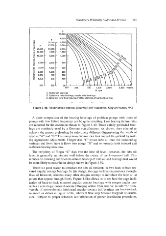
A. Radial ball bearings
B. Cylindrical roller bearings. needle roller bearings
C. Spherical roller bearings, taper roller bearings, thrust ball bearings
Figure 3-48. Relubrication interval. (Courtesy SKF Industries, King of Prussia, PA.)
A close comparison of the bearing housings of problem pumps with those of
pumps with low failure frequency can be quite revealing. Low bearing failure rates
are reported for the execution shown in Figure 3-49. These axially preloaded bear-
ings are routinely used by a German manufacturer. As shown, they elected to
achieve the proper preloading by selectively different dimensioning the width of
spacers “A” and “B.” The pump manufacturer can thus control the preload by mak-
ing appropriate adjustments. Flinger disc “C” tosses lube oil onto the surrounding
surfaces and from there it flows into trough “D’ and on towards both inboard and
outboard bearing locations.
The periphery of flinger “C” dips into the lube oil level; however, the lube oil
level is generally maintained well below the center of the lowermost ball. This
reduces oil churning and friction-induced heat-up of lube oil and bearings that would
be more likely to occur in the design shown in Figure 3-50.
There is a good reason to introduce the lube oil between the two back-to-back ori-
ented angular contact bearings. In this design, the cage inclination promotes through-
flow of lubricant, whereas many other designs attempt to introduce the lube oil at
points that oppose through-flows. Figure 3-5 la allows us to see how the cage incli-
nation of back-to-back mounted angular contact bearings with steeper angles pro-
motes a centrifugal outward-oriented flinging action from side “a” to side “b.” Con-
versely, if conventionally lubricated angular contact ball bearings are back-to-back
mounted as shown in Figure 3-51b, lubricant flow may become marginal or insuffi-
cient. Subject to proper selection and utilization of proper installation procedures,