
Page 192 - Improving Machinery Reliability
P. 192
Machinery Reliability Audits and Reviews 163
b
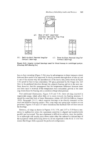
al: Skew of ball seoarator
bl : Back-to-Back Mounted Angular c) : Face-to-Face Mounted Angular
Contact Bearings Contact Bearings
Figure 3-51. Angular contact bearings used for thrust takeup in centrifugal pumps.
(Courtesy SKF Bearing Co.]
face-to-face mounting (Figure 3-5 IC) may be advantageous in those instances where
lubricant flow needs to be improved. It clearly promotes through-flow of lube oil and
is one of the reasons why the manufacturer of the heavy duty pump shown in Figure
3-52 opted for face-to-face orientation. Oil spray generated by the flinger disc will
flow in the preferred direction through the adjacent bearing and on to the next one.
Note, however, that this presupposes that the temperature difference between inner
and outer races is minimal. If the temperature were substantial, growth of the inner
ring would force the bearing into a condition of high axial preload.
Two additional illustrations, Figure 3-53 and 3-54, show oil rings inserted in
trapezoidal ramps, which allow lube oil to move towards the bearing internals. It
should be noted that both of these illustrations violate API-610 8th Edition (August
1995). Paragraph 2.9.1.3, which requires bearings to be directly mounted on the
shaft and disallows bearing carriers. Also, snap rings and spring-type washers are not
permitted. Figures 3-55 and 3-57 show executions that facilitate lube oil flow toward
the bearings.
However, oil rings as shown in Figures 3-53, 3-54, and 3-57 to 3-59 have a ten-
dency to malfunction unless the equipment centerline is aligned and installed truly
parallel and horizontal. This true alignment is difficult to achieve, since the machin-
ist or millwright will usually place shims under either the outboard or inboard legs of
the equipment while performing driver-to-driven alignment in the field. It is for this
reason that flinger disks represent the preferred configuration.