
Page 85 - Improving Machinery Reliability
P. 85
Vendor Selection and Bid Conditioning 57
ALARM RELAY
5009
FAULT-TOLERANT
CONTROL
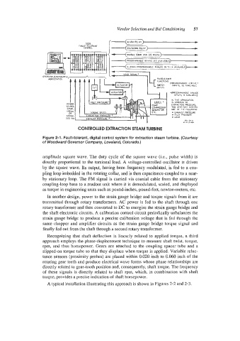
CONTROLLED EXTRACTION STEAM TURBINE
Figure 2-1. Fault-tolerant, digital control system for extraction steam turbine. (Courtesy
of Woodward Governor Company, Loveland, Colorado.)
amplitude square wave, The duty cycle of the square wave (Le., pulse width) is
directly proportional to the torsional load. A voltage-controlled oscillator is driven
by the square wave. Its output, having been frequency modulated, is fed to a cou-
pling loop imbedded in the rotating collar, and is then capacitance-coupled to a near-
by stationary loop. The Fh4 signal is carried via coaxial cable from the stationary
coupling-loop base to a readout unit where it is demodulated, scaled, and displayed
as torque in engineering units such as pound-inches, pound-feet, newton-meters, etc.
In another design, power to the strain gauge bridge and torque signals from it are
transmitted through rotary transformers. AC power is fed to the shaft through one
rotary transformer and then converted to DC to energize the strain gauge bridge and
the shaft electronic circuits. A calibration control circuit periodically unbalances the
strain gauge bridge to produce a precise calibration voltage that is fed through the
same chopper and amplifier circuits as the strain gauge bridge torque signal and
finally fed out from the shaft through a second rotary transformer.
Recognizing that shaft deflection is linearly related to applied torque, a third
approach employs the phase-displacement technique to measure shaft twist, torque,
rpm, and thus horsepower. Gears are attached to the coupling spacer tube and a
slipped-on torque tube so that they displace when torque is applied. Variable reluc-
tance sensors (proximity probes) are placed within 0.020 inch to 0.060 inch of the
rotating gear (eeth and produce electrical wave forms whose phase relationships are
directly related to gear-tooth position and, consequently, shaft torque. The frequency
of these signals is directly related to shaft rpm, which, in combination with shaft
torque, provides a precise indication of shaft horsepower.
A typical installation illustrating this approach is shown in Figures 2-2 and 2-3.