
Page 150 - Industrial Cutting of Textile Materials
P. 150
Automated cutting of textile materials 137
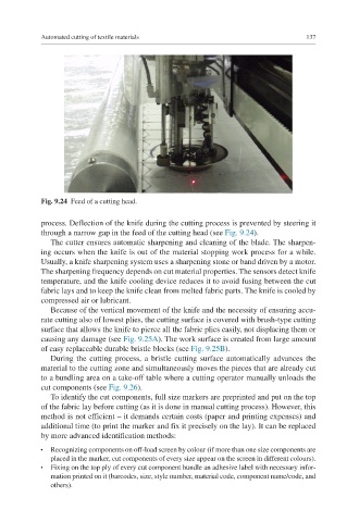
Fig. 9.24 Feed of a cutting head.
process. Deflection of the knife during the cutting process is prevented by steering it
through a narrow gap in the feed of the cutting head (see Fig. 9.24).
The cutter ensures automatic sharpening and cleaning of the blade. The sharpen-
ing occurs when the knife is out of the material stopping work process for a while.
Usually, a knife sharpening system uses a sharpening stone or band driven by a motor.
The sharpening frequency depends on cut material properties. The sensors detect knife
temperature, and the knife cooling device reduces it to avoid fusing between the cut
fabric lays and to keep the knife clean from melted fabric parts. The knife is cooled by
compressed air or lubricant.
Because of the vertical movement of the knife and the necessity of ensuring accu-
rate cutting also of lowest plies, the cutting surface is covered with brush-type cutting
surface that allows the knife to pierce all the fabric plies easily, not displacing them or
causing any damage (see Fig. 9.25A). The work surface is created from large amount
of easy replaceable durable bristle blocks (see Fig. 9.25B).
During the cutting process, a bristle cutting surface automatically advances the
material to the cutting zone and simultaneously moves the pieces that are already cut
to a bundling area on a take-off table where a cutting operator manually unloads the
cut components (see Fig. 9.26).
To identify the cut components, full size markers are preprinted and put on the top
of the fabric lay before cutting (as it is done in manual cutting process). However, this
method is not efficient – it demands certain costs (paper and printing expenses) and
additional time (to print the marker and fix it precisely on the lay). It can be replaced
by more advanced identification methods:
Recognizing components on off-load screen by colour (if more than one size components are
●
placed in the marker, cut components of every size appear on the screen in different colours).
Fixing on the top ply of every cut component bundle an adhesive label with necessary infor-
●
mation printed on it (barcodes, size, style number, material code, component name/code, and
others).