
Page 165 - Industrial Cutting of Textile Materials
P. 165
152 Industrial Cutting of Textile Materials
10.2 Automated laser cutting systems and their
main parts
A laser system consists of a laser cutting tool, an optical system to guide the laser
cutting tool, a software to control the laser, the work surface to support processed
material, and the extraction system to draw away the smoke particles and soiling cre-
ated in the laser cutting process.
10.2.1 Laser cutting tool
The laser beam is a column of very high-intensity light of a single wavelength or co-
lour. In the case of a CO 2 laser, it is an infrared light at 10.6 μm, invisible to the human
eye. During the cutting process, the light from a laser source is focused and intensified
by a lens or mirror to create a laser beam at the cut surface (see Fig. 9.14). As the in-
tense beam of light strikes the material, the temperature rises, and the material melts,
burns, and evaporates. Depending on the applied laser power level, cutting, perfora-
tion, marking, engraving, and even heat sealing of the textile materials are possible.
The main parts generating and transferring a laser beam to cut material are a laser
beam source, a laser beam guidance system, and a cutting head.
10.2.1.1 Elements of the laser beam source
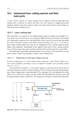
Several components of a laser beam source generate a laser beam. They are a
laser- active medium, an energy source, an optical resonator, and a cooling system
(see Fig. 10.1).
Active/gain/laser medium – Laser-active media is a gas that sends out the part of
emission energy in the form of laser radiation. The CO 2 laser beam is produced using a
gas of three components: carbon dioxide (CO 2 ), nitrogen (N 2 ), and helium (He) in the
ratio of 1:2:3 (the active centres are the carbon dioxide molecules because laser will
be achieved due to these molecules). Three gases are mixed in a sealed discharge tube.
Fig. 10.1 Schema of components generating laser beam.