
Page 166 - Industrial Cutting of Textile Materials
P. 166
Automated laser cutting of textile materials 153
Pump/energy source – High-frequency electric discharge method is used to stim-
ulate the gas mixture. The atoms and molecules of the gas try to follow the changing
polarity of the field, heat up, collide with each other, and get excited.
Optical/reflecting resonator – If the excitation energy has sufficient intensity, the
gas mixture can become a laser. To reach it, the laser beam is reflected back and forth
many times by help of mirrors placed at both ends of the discharge tube. This set of
mirrors is called the optical resonator system. One of the mirrors is completely reflect-
ing, but the other is only partially reflecting to transmit the part of the laser radiation
for further use.
Cooling system – A large quantity of heat generates in the laser tube during the
work process. In order to avoid overheating of critical components and the rise of am-
bient temperature, the heat must be removed from the discharge tube. This is accom-
plished through the use of a special temperature-stabilized air or water cooling system.
10.2.1.2 Cutting head (processing head)
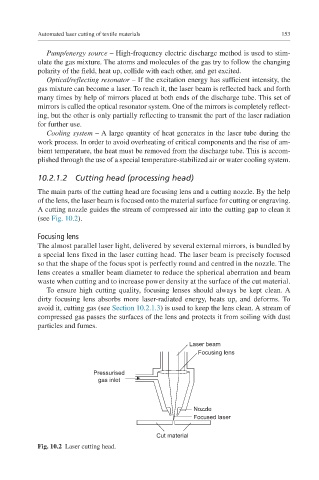
The main parts of the cutting head are focusing lens and a cutting nozzle. By the help
of the lens, the laser beam is focused onto the material surface for cutting or engraving.
A cutting nozzle guides the stream of compressed air into the cutting gap to clean it
(see Fig. 10.2).
Focusing lens
The almost parallel laser light, delivered by several external mirrors, is bundled by
a special lens fixed in the laser cutting head. The laser beam is precisely focused
so that the shape of the focus spot is perfectly round and centred in the nozzle. The
lens creates a smaller beam diameter to reduce the spherical aberration and beam
waste when cutting and to increase power density at the surface of the cut material.
To ensure high cutting quality, focusing lenses should always be kept clean. A
dirty focusing lens absorbs more laser-radiated energy, heats up, and deforms. To
avoid it, cutting gas (see Section 10.2.1.3) is used to keep the lens clean. A stream of
compressed gas passes the surfaces of the lens and protects it from soiling with dust
particles and fumes.
Laser beam
Focusing lens
Pressurised
gas inlet
Nozzle
Focused laser
Cut material
Fig. 10.2 Laser cutting head.