
Page 36 - Industrial Cutting of Textile Materials
P. 36
Lay planning and marker making in textile cutting operations 23
3.6.9 Linings
Pattern pieces for the same article may be placed in different directions if the fabric
pattern does not lie in a single direction.
3.6.10 Interlinings
Pattern pieces for the same article may be placed to lie in different directions.
3.7 Placement of the pattern pieces of fusible
components in a marker
When placing the pattern pieces of fusible components in a marker, their possible
shrinkage during the fusing process must be taken into account. Because of the wide va-
riety of textile materials, it is not usually possible to inspect every fabric and its washed
and fused fabric samples or visually predict the shrinkage volume. Therefore two-step
cutting is used for fusible components. In the first step, the components are cut slightly
bigger, giving some leeway around their edges (rough cutting; see Section 7.2.2) be-
fore the fusing process is performed. After fusing, the fine cutting is completed, and
the extra fabric remaining after shrinkage is removed (see Section 7.2.3).
There are two ways of placing pattern pieces of fusible components in a marker: by
forming a buffer (fabric allowance) around each component or by grouping them in
blocks with a buffer around their edges.
3.7.1 Formation of a buffer around the pattern pieces
of fusible components
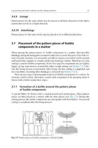
A special buffer 10–20 mm wide is created around each pattern piece. These pattern
pieces are then placed in a marker with the other pieces (see Fig. 3.7). During the
cutting process, the fusible components are cut together with their buffers. The second
cutting is completed after the fusing process.
10–20 mm
Fig. 3.7 Pattern pieces of fusible components with their buffer.