
Page 46 - Industrial Power Engineering and Applications Handbook
P. 46
Theory, performance and constructional features of induction motors 1/27
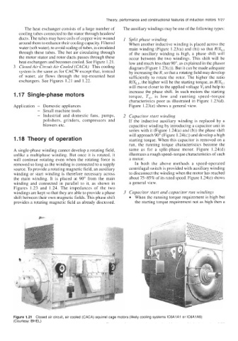
The heat exchanger consists of a large number of The auxiliary windings may be one of the following types:
cooling tubes connected to the stator through headers/
ducts. The tubes may have coils of copper wire wound I Split phase winding
around them to enhance their cooling capacity. Filtered When another inductive winding is placed across the
water (soft water), to avoid scaling of tubes, is circulated main winding (Figure 1.23(a) and (b)) so that RIX,,
through these tubes. The hot air circulating through of the auxiliary winding is high, a phase shift will
the motor stator and rotor ducts passes through these occur between the two windings. This shift will be
heat exchangers and becomes cooled. See Figure 1.21. low and much less than 90°, as explained in the phasor
3 Closed Air Circuit Air Cooled (CACA) This cooling diagram (Figure 1.23(c)). But it can be made adequate
system is the same as for CACW except that, instead by increasing the R, so that a rotating field may develop
of water, air flows through the top-mounted heat sufficiently to rotate the rotor. The higher the ratio
exchangers. See Figures 1.21 and 1.22. RIX,,, the higher will be the starting torque, as RIX,,
will move closer to the applied voltage V, and help to
1 .I7 Single-phase motors increase the phase shift. In such motors the starting
torque, T,,, is low and running speed-torque
characteristics poor as illustrated in Figure 1.23(d).
Application - Domestic appliances Figure 1.23(e) shows a general view.
- Small machine tools
- Industrial and domestic fans, pumps, 2 Capacitor start winding
polishers, grinders, compressors and If the inductive auxiliary winding is replaced by a
blowers etc. capacitive winding by introducing a capacitor unit in
series with it (Figure 1.24(a) and (b)) the phase shift
will approach 90" (Figure 1.24(c)) and develop a high
1 .I 8 Theory of operation starting torque. When this capacitor is removed on a
run, the running torque characteristics become the
A single-phase winding cannot develop a rotating field, same as for a split-phase motor. Figure 1.24(d)
unlike a multiphase winding. But once it is rotated, it illustrates a rough speed-torque characteristics of such
will continue rotating even when the rotating force is a motor.
removed so long as the winding is connected to a supply In both the above methods a speed-operated
source. To provide a rotating magnetic field, an auxiliary centrifugal switch is provided with auxiliary winding
winding or start winding is therefore necessary across to disconnect the winding when the motor has reached
the main winding. It is placed at 90" from the main about 75-85% of its rated speed. Figure 1.24(e) shows
winding and connected in parallel to it, as shown in a general view.
Figures 1.23 and 1.24. The impedances of the two
windings are kept so that they are able to provide a phase 3 Capacitor start and capacitor run windings
shift between their own magnetic fields. This phase shift When the running torque requirement is high but
provides a rotating magnetic field as already discussed. the starting torque requirement not as high then a
Figure 1.21 Closed air circuit, air cooled (CACA) squirrel cage motors (likely cooling systems IC6AlA1 or IC6AlA6)
(Courtesy: BHEL)