
Page 48 - Industrial Power Engineering and Applications Handbook
P. 48
Theory, performance and constructional features of induction motors 1/29
0- Vr(1-4) -0
Centrifugal switch
Main
Im winding opens here
Disconnect
switch
t
Start hnding
XL > XL,
R 3
Note Phase shift is obtained by increasing - P
XL1 COT,
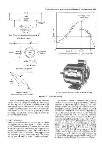
(a) Schematic diagram
Tsi
I
Speed Nr ---+ 7585% N,
(d) Speed-torque characteristics of a split phase motor
1 ; "1 I,",.
StartYwinding
(b) General arrangement
b ..
shift
..
lr
(c) Phasor diagram (e) Split phase 1-4 motor [Courtesy: AUE (GE Motors)]
Low starting and running torques
Figure 1.23 Split-phase winding
Since there is only one winding and the poles are The motor is designed conventionally, with a
already shaded at one particular end, the direction of laminated stator, a static magnetic field and a rotating
the rotating flux is fixed and so is the direction of armature, as shown in Figure 1.27(a) and (b). The
rotation of the rotor. The direction of rotation cannot armature and the field windings are connected in series
be altered as in the earlier cases. Since there is only through two brushes, fitted on the armature extended
one winding and no need of a speed-operated commutator assembly, to obtain the same direction of
centrifugal switch, these motors require almost no field and armature currents. Thus, when the direction
operational maintenance. of the line current reverses, the field and armature
currents also reverse. When operated on a.c., the torque
produced is in pulses, one pulse in each half cycle as
5 Universal motors illustrated in Figure 1.27(c). The normal characteristics
These are series motors and are relatively compact for such motors are also illustrated in Figure 1.27(d).
and lightweight compared to an a.c. motor. The use The no-load speed may be designed very high, to the
of such motors is therefore common for hand tools order of 2000-20 000 r.p.m. but the speed on load
and home appliances and also for such applications may be around 50-80% of the no-load speed due to
that require a high speed (above 3200 r.p.m) which is windage and friction losses, which constitute a higher
not possible in an a.c. machine. Likely applications percentage for such small to very small motors (l/lo
are polishers, grinders and mixers. This motor runs to 1 h.p.). The required output speed for the type of
equally well on both a.c. and d.c. sources of supply. application can be obtained through the use of gears.