
Page 596 - Industrial Power Engineering and Applications Handbook
P. 596
Voltage surges-causes, effects and remedies 171561
for a 12/50 ps voltage surge and 3W60 ps for a
vt
250/2500 ,us voltage surge r.r.r.v. = - kV/ps
t, = 1.25 x time taken by the current to increase tl
from 10% to 90% of its peak value. The significance of this term can be realized by the fact
2 t2 = time interval between the origin and the instant that the voltage stress of a surge, having a maximum
at which the impulse has decreased to half of its amplitude of 4.5 P.u., with a front time t, of 5 ,us, will
peak value. roughly be the same or even less severe compared to a
surge with an amplitude of only 2 p.u. and a front time
of 0.2 ps (see Insulation Sub-committee, Rotating
17.6.2 Transient recovery voltage (TRV) and its Machinery Committee, 198 1).
rate of rise (r.r.r.v.) in an induction motor When a fault occurs near the source of supply, the line
lumped leakage capacitance C is small and the frequency
This is an important parameter. A very fast-rising transient of oscillations high. of the order of a few kHz (equation
can cause the surge voltage to be non-uniformly distributed (17. I)). But when the fault occurs at a distance from the
over the entire length of the motor windings and affects source, C tends to become higher and the frequency of
the first or the entrance coil of the motor windings, as oscillations lower, of the order of a few hundred Hz. An
discussed in more detail in Section 17.8. This is the introduction of some resistance in the interrupting circuit
voltage t V,) that will reappear immediately on a current will tend to dampen (attenuate) the oscillations but where
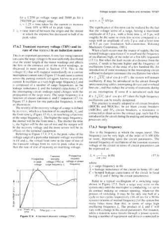
interruption (current zero) (Figure 17.4) and cause a current
across the parting contacts yet again, known as post-arc R > 2 (@of cos 4 > 45"). the system will remain
current. It oscillates at a very high surge frequencyf, and oscillatory. R may be introduced in the circuit through
is composed of a number of surge frequencies, as the interconnecting cables, interrupting devices and overhead
leakage inductance L and the lumped capacitance C of lines etc., and thus reduce the severity of transients during
the interrupting circuit undcrgo rapid changes with the an arc interruption. If some R is introduced such that
propagation of the surge wave. The surge frequency is a R > 2- (4 of cos 4 < 45") then the high-frequency
function of circuit constants L and C (equation (17. I)).
Figure 17.4 drawn for one particular frequency, is only oscillations can be totally dampened.
an illustration. This practice is usually adopted in oil circuit breakers
The severity of the recovery voltage of a surge is defined (BOCBs and MOCBs). In air blast circuit breakers
by its r.r.r.v., which is a function of its amplitude, V,, and (ABCBs), and SF6 circuit breakers, a resistance is
the front time tl (Figure 17.4), tl in turn being a function connected in shunt across the contact gap, such that R is
of the surge frequencyf;. The higher the surge frequency, introduced in the circuit during the making and interrupting
the shorter will be the front time tl. The shorter the time processes only.
f,, the higher will be the rate of rise and the steeper will
be the recovery voltage and the more severe will be its 17.6.3 Surge frequency
effects on the terminal equipmcnt. This is the frequency at which the surges travel. This
Referring to Figure 17.4, if V, is the peak value of the
voltage surge of a particular transient voltage waveform frequency can be very high. of the order of 5-100 kHz
or more, depending upon the circuit parameters. The
in kV and tl, the virtual front time or the time of rise of
the transient voltage from its zero to peak value in ps, natural frequency of oscillations of the transient recovery
voltage of the circuit in terms of circuit parameters can
then the rate of rise of recovery or restriking voltage,
be expressed as:
Transient Prospective (17.1)
Prospective recovery recovery
or peak voltage (TRV) at voltage at Power where
voltage surge frequency 6 frequency
f; = surge frequency in Hz
L = leakage inductance of the circuit in henry (H ) and
C = lumped leakage capacitance of the circuit in farad
(F) (L and C being the circuit parameters).
Refer to a typical oscillogram of a switching surge
shown in Figure 17.5. Such a surge may exist on the
system only until the interrupter is conducting, i.e. up to
its contact making or contact opening, whatever the
process of switching. It may be for only one half of a
cycle to two cycles respectively (10-40 ms for a SO Hz
system) in terms of normal frequencyJof the system but
many times more than this, in terms of surge high
oscillating frequency f?. The product of L and C will
- ~ront -I t, Time (p- vary with a change in thc circuit parameters. For instance,
time
when a transient wave travels through a power system,
Figure 17.4 A transient recovery voltage ('TRV') having a number of equipment and devices connected to