
Page 781 - Industrial Power Engineering and Applications Handbook
P. 781
v I I
j Carrier ,
' j equipment I
coupling '
~ I
I arrangement ,
i
2 D-nding I switch for
I maintenance
I
Carrier frequency ,
I
I
Communication
network (PLCC)
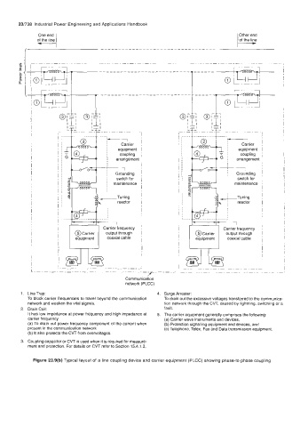
1. LineTrap: 4. Surge Arrester:
To block carrier frequencies to travel beyond the communication To drain out the excessive voltages transferred to the communica-
network and weaken the vital signals. tion network through the CVT, caused by lightning, switching or a
2. Drain Coil: fault.
It has low impedance at Power frequency and high impedance at 5. The carrier equipment generally comprises the following:
carrier frequency (a) Carrier wave instruments and devices,
(a) To drain out power frequency component of the current when (b) Protection signalling equipment and devices, and
present in the communication network (c) Telephone, Telex, Fax and Data transmission equipment.
(b) It also protects the CVT from overvoltages.
3. Coupling capacitor or CVT is used when it is required for measure-
ment and protection. For details on CVT refer to Section 15.4.1.3,
Figure 23.9(b) Typical layout of a line coupling device and carrier equipment (PLCC) showing phase-to-phase coupling