
Page 784 - Industrial Power Engineering and Applications Handbook
P. 784
Power capacitors. behaviour, switching and improvement of power factor 23/741
All such harmonics are undesirable for the system and
the equipment connected to it. Refer to Table 23.1 for
the likely magnitudes of harmonic quantities which may
be present in a typical power system.
23.6.1 Theory of circulation of triple harmonic
quantities in an a.c. system
Triple harmonic quantities are unbalanced quantities and
can exist only on a system, which has a grounded neutral.
The configuration of the windings of the source generating
the harmonics. the system to which it is connected, and
8- 1
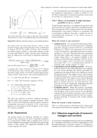
Form factor = % = 1 .ll Rectifier factor = - 1.57 its grounding conditions, thus play a significant role in
=
21a 2ix
transmitting the harmonics to the whole system as
Note When referring to the d c side, it is the mean value and when
referring to the a c side. it is the effective value that IS more relevant discussed below:
Figure 23.11 Effective and mean values in a sinusoidal waveform When the system is star connected
Isolated neutral In a symmetrical three-phase three-
the nearer will the mean and effective values of the wire star-coiinected system the summation of all phase
rectified voltages approaching the peak value. as illustrated quantities, voltage or current will be zero, as illustrated
in Figure 23.10. Six pulse rectifiers are therefore in Figure 2 I .7. When a few harmonics exist in such a
considered ideal 10 achieve a near-peak voltage in both system, this balance is disturbed and the sum of these
its mean and effective values and are more commonly quantities is riot zero. The third harmonic quantities
used. In which case: form factor or harmonic distortion can find their outlet only through a neutral of the
factor system. Since there is no neutral available in this
system, no third harmonic quantities will flow into or
Eftective value (r.m.\. value of all harmones = 1.0009 out uf the supply system and affect the equipment
Mean value associated with it or a communication network if
Peak value ,05 existing in the vicinity (Figure 23.12(a)).
and rectifier peak factor. i.e. ~
Mean value Ungrounded neutral (floating neutral) However,
as against the values indicated in Figure 23.1 I. Figure when the neutral is provided. each phase can complete
23. IO illustrates some common types of pulse numbers. its own circuit through the neutral. provided the
the likely shape of their waveforms and the approximate connections are made so that it can complete its circuit
valucs of their ‘form factors’ and ‘rectifier peak factors’. through the neutral. The supply system would contain
no third harmonic, as it cannot drainout this through
k = 1st. 2nd. 3rd. and 4th etc. waveforms a floating neutral. The supply system. being balanced.
For X. = 1 and 2, the harmonic sequence will be would contain no harmonic as noted above. In each
phase to neutral, however, the third harmonic may
exist but of a lesser magnitude, deperidirig upon the
(i) for a three-phase thyristor circuit impedance of the system. (Figure 23. I2(b)).
3 x k I. i.e. 2 and 4, and Grounded neutral When the neutral is grounded.
3 x 2 t I. i.e. 5 and 7. etc. the third harmonic quantities will be able to find their
(ii) for a hexaphase thyristor circuit way through it. This system can thus be considered to
I
6 x I f = 5 and 7. and contain the third harmonic quantities and will affect
6 x 2 t 1 = 1 I and 13. etc. operation oftheequipmentconnected onit and commu-
nication networks if existing in the vicinity (Figure
The plus sign indicates a positive sequence harmonic 23.12(c)).
and the minus sign a negative sequence harmonic. Their
effect is same as for the positive and the negative sequence When the system is delta connected
components disciissed in Section 12.2(v) and causes
pulsation in the magnetic field and hence, in thc torque This is a similar system to that discussed in 1 above and
of a rotating machine. will contain no third harmonic quantities (Figure 23.12(d)).
23.6~ Resonance 23.7 Effective magnitude of harmonic
voltages and currents
Yet another reason for harmonic disorder in a power
circuit is the occurrence of series or parallel resonance
or a combination of both. Such a situation may occur at A waveform containing harmonics may be considered to
certain frequencies generated by the harmonic generating be a standard sinusoidal waveform superimposed with
sources in the system. The capacitors installed in the the other harmonic waveforms. Figure 23.7 illustrates a
sy\tem magnify the same. standard sinusoidal waveform, superposed with third and