
Page 783 - Industrial Power Engineering and Applications Handbook
P. 783
23/740 Industrial Power Engineering and Applications Handbook
By the harmonic fzux and frequencies regulation, they may cause excessive voltages during
Increased iron losses in the inductive machines, operating offpeak periods, resulting in an oversaturation of the
on such a system, due to saturation effects (equations transformer cores and the generation of triplc harmonics.
(1.12) and (1.13).
23.6b Generation of harmonics by a
23.6a Generation of triple harmonics power electronic circuit
in an inductive circuit
Another reason for harmonic disorders is the presence of
A hysteresis loss in an electromagnetic circuit will occur power electronic circuits in the system. The loads supplied
due to molecular magnetic friction (magnetostriction), through solid-state devices such as thyristors generate
as discussed in Section 1.6.2(A-iv). This causes a distortion non-sinusoidal waveforms. These waveforms give rise
in voltage and current by distorting their natural sinusoidal to harmonic currents and distort the supply voltage. Line-
waveforms. This distortion in the natural waveforms, in commutated converters and frequency converters
terms of magnetizing current I,, induced e.m.f. e and employed for a.c./d.c. drives, electrolytic processes,
magnetic flux $J of the magnetic circuit is the source of inverters, a.c. controllers, d.c. choppers, cyclo-converters,
generating triple harmonic quantities, the magnitude of and SCR rectifiers (for details refer to Chapter 6) are
which will depend upon the shape of the hysteresis loop, examples of electronic applications that may generate
which is a function of the core material. A fluctuation in harmonic quantities and influence the normal current
the system voltage which causes a change in the flux drawn by a power capacitor. With advances in power
density B (equation (1.5)) also adds to the triple harmonic electronics, modern power systems have a wider
quantities. Permeability ,u of the magnetic core is different application of solid-state technology in the control of
at different flux densities B. This results in giving rise to induction motors and d.c. motor drives as discussed in
triple harmonics due to magnetic friction (magneto- Section 6.9. There is therefore more likelihood of the
striction). Wherever the switching of a capacitor bank is presence of harmonics in the system that may result in
more frequent, the generation of triple harmonic voltages high to very high harmonic currents and consequent
is more severe. harmonic voltages. This effect is felt more on LT and
Uneven distribution of loads causes an imbalance in the also HT systems up to 11 kV where use of static controls
supply system which also generates triple harmonic is more prominent. For the harmonics generated by power
voltages. This is more pronounced in LT systems than in electronic circuits, the harmonics ordinal numbers that
HT systems due generally to fewer switching operations may be present in the system are expressed by
and an almost balanced load distribution in HT systems
(also refer to Table 23. I). But an HT system too is not free harmonic ordinal number Nh = nk f 1
from third harmonics due to unequal overhead line where n = pulse number; 3 for a three phase and 6 for a
impedances which may be caused by unequal spacings hexaphase power electronics circuit, etc.
between the horizontal and vertical formation of conductors,
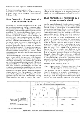
asymmetrical conductor spacings and hence an unequal This represents the type of converter connection and
induced magnetic field. Overexcitation of transformer identifies the number of successive commutations (Le.
cores, which may be a result of voltage fluctuations or a the number of discrete segments of the d.c. waveform,
load rejection, may also cause triple harmonic voltages. Figure 23.10) the rectifier unit will conduct during each
When capacitors are used to improve the system's cycle of a.c. power input. The higher the pulse number,
Likely waveforms generated by a rectifier unit in its output
for each cvcle of a.c. inout. for different numbers of Dulses
Parameters
Form factor 1.57 I 11.017 I 1.0009 1
Effective value' or harmonic 1.11 1.00005
3.14 1 1.57 1 1.21 1 1.05 1
Mean value I distortion factor
(Rectifier peak factor) 1.01
* - rrns value of all harmonics
Figure 23.10 The content of ripples for different number of pulses (n)