
Page 788 - Industrial Power Engineering and Applications Handbook
P. 788
23/744 Industrial Power Engineering and Applications Handbook
23.7.1 Recommended magnitudes of harmonic
disorders
For safe operation of power and control equipment and
devices operating in such systems it is essential to limit
the amplitude of the voltage distortions to a safe value
by installing filter circuits based on the system's actual
operating conditions. These limits are recommended by
leading standards organizations are:
1 UK engineering recommendation - G5/3 (British
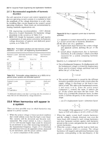
Electricity Council Standard). For harmonic voltage Figure 23.13 Rise in apparent current due to harmonic
distortions in the system as in Table 23.2. quantities
2 IEEE-519: Guide for harmonic control and reactive
compensation of static power converters, for harmonic I, = apparent or current measured by an ammeter
voltage distortions of general and dedicated power Ih = actual current due to harmonic distortions
system, as in Table 23.3. All the above are r.m.s. quantities.
@ = displacement angle between the system voltage
and apparent current, defining the p.f. of the
Table 23.2 Premissible individual and total harmonic voltage load
distortions - as in G5/3, UK engineering recommendations
6 = actual phase displacement due to harmonic
distortions. It is the actual p.f. which is less than
Nominal system Individual harmonic voltage 7imd harmonic measured for a system containing harmonic
voltage distortions distortions
~~ disorders.
kV Odd( 70) Even (lo) %
Quantity Ih is composed of two components:
0.415 4 2 5
6.6-1 1 3 1.75 4 One at fundamental frequency. Its displacement with
33-66 2 I 3 the fundamental voltage is termed the displacement
132 1 0.5 I .s factor, and for a linear voltage and linear load will
define the p.f. of the load, i.e.
Table 23.3 Premissible voltage distortions as in IEEE-519 for
general power systems and dedicated systemsa
The second component is caused by the different
Nominal system General power Dediccrred harmonic quantities present in the system when the
voltage systems rystems supply voltage is non-linear or the load is non-
kV lo 96 linear or both. This adds to the fundamental current,
~-
~~~ I, and raises it to Ih. Since the active power
2.449 5 8 component I, remains the same, it reduces the
1 15 and above 1 .s 1 .s
p.f. of the system and raises the line losses. The
A dedicated system is one that is servicing only the converters or factor IJIh is termed the distortion factor. In other
loads that are not influenced by voltage distortions. words, it defines the purity of the sinusoidal wave
shape.
23.8 When harmonics will appear in :. cos 6 = displacement factor x distortion factor
a system
There are three possible ways in which harmonics may
appear in a power system: For example, if the apparent p.f. is 0.9, a distortion
factor of 0.85 will reduce it to 0.9 x 0.85 or 0.765.
1 When the system voltage is linear (an ideal condition 2 When the supply system itself contains harmonics
that would seldom exist) but the load is non-linear: and the voltage is already distorted: now even the
The current will be distorted and become non- linear loads will respond to such voltage harmonics
sinusoidal. The actual current I,, (r.m.s.) (equation and draw harmonic currents against each harmonic
(23.2)) will become higher than could be measured present in the system, and generate the same order of
by an ammeter or any other measuring instrument, at current harmonics.
the fundamental frequency. Figure 23.13 illustrates 3 When the system voltage and the load are both non-
the difference between the apparent current, measured linear: a condition which is common. The voltage
by an instrument, and the actual current, where harmonics will magnify and additional harmonics may
1, = active component of the current generate, corresponding to the non-linearity of the