
Page 791 - Industrial Power Engineering and Applications Handbook
P. 791
Power capacitors: behaviour. switching and improvement of power factor 23/747
When such a reactance is used to suppress the system Vph = system voltage
harmonics it will resonate at a frequency fh such that
Vc = voltage across the capacitor banks = IC. Xc
VL = voltage across the series reactor = I,. XI-
where
X, = capacitive reactance
XL = inductive reactance. and
I, = current through the capacitor circuit
then
- '0 for a SO HZ system
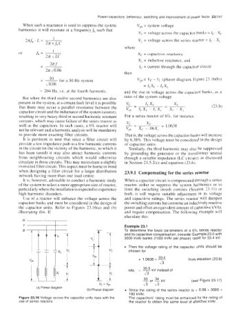
- Vph = Vc - Vl~ (phasor diagram, Figure 23.16(b))
0.06 = ICXC - ICX,
= 204 Hz. i.e. at the fourth harmonic. and the rise in voltage across the capacitor banks. as a
But when the third and/or second harmonics are also ratio of the system voltage
present in the system, at a certain fault level it is possible k- - XC
IC&
that there may occur a parallel resonance between the Vp, - - x, -x, (73.8)
capacitor circuit and the inductance of the system (source), I,X, -1, XL
resulting in very heavy third or second harmonic resonant For a series reactor of 6%. for instance.
currents. which may cause failure of the series reactor as
-
well as the capacitors. In such cases, a 6% reactor will 2- xc = 1.0638
not be relevant and a harmonic analysis will be mandatory Vph X, - .06X,
to provide more exacting filter circuits. That is, the voltage across the capacitor banks will increase
It is pertinent to note that since a filter circuit will by 6.38%. This voltage must be considered in the design
provide a low impedance path to a few harmonic currents of capacitor units.
in the circuit (in the vicinity of the harmonic, to which it Similarly, the third harmonic may also be suppressed
has been tuned) it may also attract harmonic currents by grounding the generator or the transformer neutral
from neighbouring circuits which would otherwise through a suitable impedance (LC circuit), as discussed
circulate in those circuits. This may necessitate a slightly in Section 23.5.2(c) and equation (23.6).
oversized filter circuit. This aspect must be borne in mind
when designing a filter circuit for a larger distribution 23.9.1 Compensating for the series reactor
network having more than one load centre.
It is, however, advisable to conduct a harmonic study When a capacitor circuit is compensated through a series
of the system to select a more appropriate size of reactor, reactor, either to suppress the system harmonics or to
particularly where the installation is expected to experience limit the switching inrush currents (Section 73.1 I) or
high harmonic disorders. both, it will require suitable adjustment in its voltage
IJse of a reactor will enhance the voltage across the and capacitive ratings. The series reactor will dampen
capacitor banks and must be considered in the design of the switching currents but consume an inductively reactive
the capacitor units. Refer to Figures 23.16(a) and (b) power and offset an equivalent amount of capacitive kVAr.
illustrating this. If and require compensation. The following example will
elucidate this.
R I Example 23.1
1. To determine the basic parameters of a 6% series reactor
and its capacitive compensation, consider Example 23.6 with
3000 kVAr banks (1000 kVAr per phase) rated for 33.4 kV:
Then the voltage rating of the capacitor units should be
ri chosen for 33.4 from equation (23.8)
= 1.0638 x Y
>/ 3
i
'WXL say, = ~ 35.5 kV instead of
>b
33
34
or
\3
73
VC > voh - = kV (see Figure 23.1 7)
(a) Power diagram
(b) Phasor diagram Since the rating of the series reactor is = 0.06 x 3000 =
180 kVAr.
Figure 23.16 Voltage across the capacitor units rises with the The capacitors' rating must be enhanced by the rating of
use of series reactors the reactor to obtain the same level of effective kVAr.