
Page 796 - Industrial Power Engineering and Applications Handbook
P. 796
23/752 Industrial Power Engineering and Applications Handbook
where close proximity with another set of banks of almost similar
f, = switching or transient frequency capacity such as a capacitor control panel, having a set
f = power frequency of capacitor banks arranged to switch ON and OFF,
X, = power frequency capacitive reactance of the circuit, depending upon load variations of that circuit. Capacitor
and units installed on the same system but not in close
X, = power frequency inductive reactance of the circuit. proximity may not influence the switching behaviour of
these capacitor units as severely as when they are installcd
Switching overvoltage in close proximity due to the extra line impedance thus
introduced.
This is seen to rise up to 1.8-2 p.u. of the peak applied
voltage, Vp, when switching an uncharged capacitor and Inrush current
around 2.6-3 p.u. when switching an already charged
capacitor (Section 23.5.1). In this switching, the cumulative effect of the applied
voltage and the trapped charge of the already charged
Rating of the switching device capacitors is of little relevance but the resultant current
is extremely high as derived below.
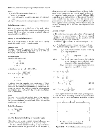
This is as recommended in Section 25.6 and is equally Consider a typical circuit as shown in Figure 23.21:
applicable to LT and HT capacitor units.
=- VP (when the applied voltage was at its peak and
Example 23.3 In Z, the switching capacitor had no trapped charge)
Consider the same LT system of 41 5 V, as of Example 23.8, where I, = peak inrush current in parallel switching
three-phase 50 Hz, and having a fault level of 36 MVA and Z, = surge impedance
employing capacitor banks of 360 kVAr.
- I L2 (equation (17.2))
-
Inrush current dC"q
Capacitor full-load current
where L2 = circuit inductance between the banks in
360 henry (ignoring the negligible self-
I, =
& x 0.415 inductance of the capacitor banks)
Ceq = equivalent series capacitance of the two
= 500 A
capacitors C, and C, in farad
and static current I, = & x 500 = 707 A
and I,,, = 707[ 1 + IF)
= 707 (1 + 10)
= 7777 A
or eleven times the capacitor peak rated current. This is (23.12)
when totally uncharged capacitors are switched. If the
capacitors are already charged when they are switched, the I,, = Vp JLzz
inrush current may rise up to twice this, Le. almost twenty- (23.13)
two times the rated peak current (but not exceeding the fault and
level of the system).
This is a generalized formula to simplify the equation.
Note In fact, the actual switching current will be much less
Here we have considered the fault level of the switching than this, due to circuit impedance. For more accurate
circuit to be same as that of the entire system, as they are
the total capacitor banks connected in the system and switched
together as a single unit.
Switching frequency
= 500 HZ
23.10.2 Parallel switching of capacitor units
This shows yet more complex circuit behaviour and Parallel operation of capacitor bank C, I
requires more detailed analysis as discussed below. with an already switched capacitor C,
We have considered the switching of capacitor banks
that are installed on one power circuit and mounted in Figure 23.21 A simplified capacitor switching circuit