
Page 798 - Industrial Power Engineering and Applications Handbook
P. 798
23/754 Industrial Power Engineering and Applications Handbook
Notes than in an LT system. An HT system will have a
1 For air break LT switches and contactors IEC 60947-3 and IEC much smaller impedance, 2, compared to the applied
60947-4-1 have specified the making capacities for heavy-duty voltage, V,, than an LT system, which will have a
AC-3 components as follows (also refer Lo Section 12.10): much higher value of Zcompared to the applied voltage
(i) For rated current up to 100 A - 10 times the r.m.s. value
(ii) For rated currents beyond 100 A ~ 8 times the r.m.s value "P.
The manufacturers of such devices, however, may declare
the making capacity of such devices to be even higher Thus, the analysis conducted above to derive I, on a
than this when the higher value may be considered to parallel switching is more pertinent for an HT system,
design the inductance, to limit the inrush current (Section and offers only a theoretical analysis for LT systems.
23.1 1). Nevertheless, for large LT installations such as, 2000-
(iii) Light-duty switches and contiactors up to AC-2 duty are 2500 kVA for a single circuit, as discussed in Section
not suitable for such applications.
2 NEMA publication ICS.2-210 for general-purpose contactors 13.4.1(5), employing large capacitor banks close to the
provides data for ratings prevalent in the USA. These data are feeding transformer, it may be desirable to limit the inrush
summarized as follows: current to a desirable level on the LT side also. In all
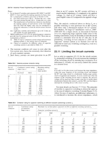
(i) Table 23.4 gives continuous current ratings and maximum probability, switching devices selected at 150% of thc
making currents, I,, for various sizes of contactors. capacitors' normal current as in Section 25.6 will be
(ii) Choice of contactors for different values of capacitor sufficient to meet any switching contingency, even on a
switching currents is provided in Table 23.5. parallel switching.
4 The transient condition will cease to exist after the
first current zero, hence the extremely short duration 23.1 1 Limiting the inrush currents
of such transient currents.
5 Such heavy currents are more prevalent in an HT
Let ub refer to equation (23.13) for the inrush current,
I,, on parallel switching. If we can increase the impedance
of the switching circuit by introducing a resistance R or
inductance L, or both, we can easily control this current
to a desired level.
Size of Continuous current rating Maximum making
contactor Amps (rm s ) current, I, Nore
Amps (peaky) If we add L or R in the circuit it will increase the surge impedance,
Eri~lused Open reduce the surge frequency of the switching circuit, and dampen
8" 1 9 10 87 small in magnitude and steepness. At every current zero when the
the 90' lead surge current to a moderately leading surge current,
contacts of the switching device tend to separate, the recovery
18
140
30
1 21 20 288 voltage will be much less than its peak value due to smaller phase
2 45 50 483 displacement between the current I,,, and the TRV, and thus help to
3 90 100 941 interrupt the switching device with a lesser severity.
4 135 1 50 1581
5 270 300 7163 For more details see Section 17.7.2(iii). The principle
6 540 600 6326 of restrike in capacitive switching is almost the same as
7 810 900 9470 in the case of inductive switching. Consider Figure 23.23,
8 1215 1350 14,205 where for ease of analysis, an additional inductance, L,
9 1 2250 2500 25,380
is introduced to increase the circuit impedance, which
Table 23.5 Contactor rating for capacitor switching at different transient (switching) currents I,,,
Size of Continuous rating Maximum size of three-phase capacitors in kVAr at different switching currents I,
contactor of contactor.y
Amps (rm.s.) Capacitor switching curreiit I,
~.
3000 5000 IO 000 14 000 18 000 22 000
A A A A A A
45 25 16 8 6 4 4
90 53 53 31 23 18 15
135 80 80 80 61 49 41
270 160 160 160 160 160 149
540 320 320 320 320 320 320
810 480 480 480 480 480 480
1215 720 720 720 720 720 720
2250 1325 I325 1325 1325 1325 1325