
Page 802 - Industrial Power Engineering and Applications Handbook
P. 802
23/758 Industrial Power Engineering and Applications Handbook
Conversion from delta to star
L=-. 4’N2 r(1og. o,7&8y- r, - 2
10’
Whenever an electrical network has different con-
figurations, such as star and delta, it must first be converted where
to an equivalent star or delta before conducting any L = self-induced inductance of the coil in henry
analysis. As derived above, the following rules of thumb N = number of turns of the coil
may be applied: r = mean radius of the conductor in cm and
1
Reactances in star = - x reactances in delta r, = radius of the cross-section of the cable in cm
3
Example 23.5 (see Example 23.4)
1
i.e. L’=-L For obtaining a self-inductance of 42.93 pH consider a coil of
3 15 cm mean diameter (r= 7.5 crn) made of the same cable
and capacitance in star = 3 x capacitance in delta, i.e. that is connecting each capacitor bank through the switching
C’ = 3c device.
where L = inductance in A per phase
L‘ = inductance in Y per phase
C = capacitance in A per phase
C’ = capacitance in Y per phase
23.11.1 Transient-free switching
With the use of static switchings through IGBTs or
thyristors (SCRs), as discussed in Sections 6.9 and 24.10
both switching overvoltages and inrush currents can be
completely eliminated. Switching are now possible at
the instant the applied voltage wave passes through its
natural zero. Since such a switching scheme is free from (a) Select a cable of 50 mrn2 of copper, rated for almost 125
any overvoltage or inrush currents, the number of A at 45°C ambient. This cable can also withstand a short-
switching operations is no problem. Also refer to Section time current of @ x 1000A for a few seconds. See also
6.16.1 on soft switchings. Section 28.4.1, the graph of Figure 28.5, and Section
Although costlier, when a smoother and faster p.f. A16.7,
correction is desirable, without causing an overvoltage ‘ -. x 1 Ji = 0.12
4
or inflow current, static switchings should be chosen. where 50
They have most application in large automatic reactive or t = 18 seconds
power controls, as discussed in Section 24.10. using a PVC insulated flexible copper cable, having a
nominal outer diameter of 12 mm and an insulation
thickness of 1.4 mm (typical).
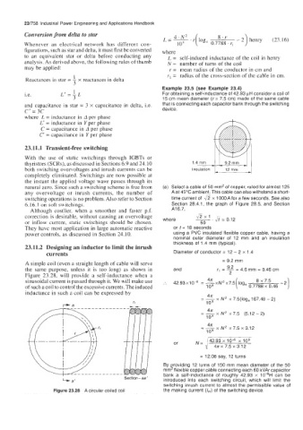
23.11.2 Designing an inductor to limit the inrush
currents Diameter of conductor = 12 - 2 x 1.4
= 9.2 mm
A simple coil (even a straight length of cable will serve
9.2
the same purpose, unless it is too long) as shown in and r, = - 4.6 mrn = 0.46 cm
=
Figure 23.28, will provide a self-inductance when a 2
41T
=
sinusoidal current is passed through it. We will make use :. 42.93~10~ -xN’x7.5 log,
of such a coil to control the excessive currents. The induced 109 ( 0.7788 x 0.46
inductance in such a coil can be expressed by 4n
-_
- x N‘ x 7.5(10ge 167.48 - 2)
109
4n
--
- x N’ x 7.5 (5.12-2)
109
48
= - N2 x 7.5 x 3.12
x
109
42.93 x lo4 x lo9
or
”=y 41~~7.5~3.12
= 12.08 say, 12 turns
By providing 12 turns of 150 rnm mean diameter of the 50
mm2 flexible copper cable connecting each 60 kVAr capacitor
bank a self-inductance of roughly 42.93 x 10⁴H can be
Section-aa’
4 a’ introduced into each switching circuit, which will limit the
switching inrush current to almost the permissible value of
Figure 23.28 A circular coiled coil the making current (I,,,) of the switching device.