
Page 801 - Industrial Power Engineering and Applications Handbook
P. 801
Power capacitors: behaviour, switching and improvement of power factor 23/757
devices such as the switch or the contactor will generally
have a making capacity of nearly eight times (peak value
fi x 8) its normal rating. (See the note below.) These data
are provided by the component manufacturers. Let us therefore
assume that /;
is to be restricted up to & x 125 x 8, Le.
t 0.413 pH may be obtained from the manufacturers' catalogues).
& x 1000 A (the actual value may be more than this, which
Therefore, in the above case,
415 V 1 415' x2x5x9x12Ox5-~
I 9 x 120pH L=
3 x 6 x 6 x 2 x 1000' 3 pH
0.4
= 43.06 - - pH
3
or 42.93 pH
If we are able to provide an inductance of this value with
415 V each capacitor bank of 60 kVAr the problem of excessive
-
$ inrush transient current can be overcome and the component
ratings as chosen above will be sufficient to switch a parallel
circuit.
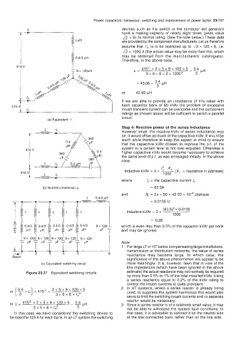
(a) Equivalent A
Step 4: Reactive power of the series inductance
However small, the reactive kVAr of series inductance may
be, it would offset as much of the capacitive kVAr. It would be
worth while therefore to keep this aspect in mind to ensure
that the capacitive kVAr chosen to improve the p.f. of the
system to a certain level is not over-adjusted. Otherwise a
415 V higher capacitive kVAr would become necessary to achieve
I the same level of p.f. as was envisaged initially. In the above
case,
1: .x,
Inductive kVAr = 3 x - reactance in Wphase]
=
[X,
1000
where /, = the capacitive current I,
(b) Normal connection A = 83.5A
and x, = 2n x 50 x 42.93 x Wphase
L 0.413pH
= 0.0135 n
(83.5)'~ 0.0135
:. Inductive kVAr = 3 x
1000
= 0.28
J
which is even less than 0.5% of the capacitor kVAr per bank
9 x 120
and may be ignored.
i Note
1 For large LT or HT banks compensating large installations,
-1 3 4 5 6 transmission or distribution networks, the value of series
reactance may become large. In which case, the
Steps
significance of the above phenomenon will appear to be
(c) Equivalent switching circuit more meaningful. It is, however, seen that in view of the
line impedances (which have been ignored in the above
Figure 23.27 Equivalent switching circuits estimate) the actual reactance may not normally be required
by more than 0.5% to 1 Yo of the total installed kVAr. Using
a series reactance equal to 0.2% of the kVAr rating to
control the inrush currents is quite prevalent.
+
or [y L) = 415' x 2 x 5 x 9 x 120 x 5 2 In HT systems, where a series reactor is already being
used, to suppress the system harmonics this would also
3x6~6~1;~
serve to limit the switching inrush currents and no separate
reactor would be necessary.
-Ep~
or L= 415* ~2~5~9~12OX5 3 Since a series reactor is of a relatively small value, it may
3x6x6xI&' 3 not be able to withstand the system fault conditions. In
In this case we have considered the switching device to that case, it is advisable to connect it on the neutral side
be rated for 125Afor each bank. In an LTsystem the switching of the star-connected bank rather than on the line side.