
Page 799 - Industrial Power Engineering and Applications Handbook
P. 799
Power capacitors: behaviour, switching and improvement of power factor 231755
Ll and Xc = 1
T- ~ 2n. f- c
I I ;_ X' -'x-- 1 - 1
I - 3 2n.f.C 2~-F.C'
I 1 :. equivalent C' = 3 C
V c1
I T c2 T
i.e. inductance of each phase in star L' = 1.2 pH
3
= 0.4 pH
and capacitance of each phase in star C' = 3 x 120 pF. For
60 kVAr bank, the equivalent circuit can be drawn as shown
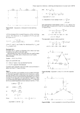
Figure 23.23 Inductance L introduced into the switching in Figure 23.25.
circuit 1
L'= _- o: pH
-
-I.++ 1 +- 1
0.4 0.4 0.4
will also dampen the resonant frequency of the switching and C' = 3 x 120 + 3 x 120 + 3 x 120
circuit. The improved I,',, of equation (23.13) can now
be expressed as: = 3 x 3 x 120 pF
The equivalent values in delta would be
(23.15) 1
L= = - 0 4 pH
1.2
or
1
~- +--+ 1 3
where L7 and Ci can further be substituted by LIeq and 1.2 1.2 1.2
C,,,, respectively. and C= 120 +120+120=36OpF
Example 23.4
Consider the Ll system of Example 23.8, where we have
considered six banks of 60 kVAr each.
Assume that three units of 20 kVAr each are used to make
each bank of 60 kVAr, and let there be six such banks.
Data available:
415 V
System - 415 V, 3-4, 50 Hz
Each unit of 20 kVAr has
C = 120 pf Typical, may be obtained from the
L = 1.2 pH I capacitor manufacturer
415 V
Consider each capacitor unit of 20 kVAr to be connected in
delta, as shown in Figure 23.24(a). L B 17
Step 1 Figure 23.24(a) Equivalent A circuit for a 20 kVAr capacitoi
There will be three such parallel circuits to make it 60 kVAr. unit
lo calculate equivalent capacitance and reactance in delta,
we may convert it into an equivalent star as shown in Figure
23.24(b) by maintaining the same line parameters as in Figure
23.24(a). If the impedance of each phase in delta is Z, then
in star also
to maintain the same steady-state line current, I/;,
let the equivalent impedance of each phase in star be 2. Then,
415
/s (delta) = ~ ,#3
# -
Z
41 5
and /,(star) = __ 415 V
23 Z'
or 415 43 = 415
Z ,3 Z'
or Z'= 1.
3
415 V
Since Xc=27r.f.L _.. x; =Ix2a f L &
3 _tB -
1
equivalent L' will be = -L
3 Figure 23.24(b) A clrcuit, equivalent to A circuit of Figure 23.24(a)