
Page 795 - Industrial Power Engineering and Applications Handbook
P. 795
Power capacitors: behaviour, switching and improvement of power factor 23/751
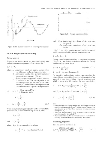
4 In ,, Charging current :
I
V
I T
1-
Time - Figure 23.20 A single capacitor switching
Z,, = short-circuit impedance 01 the .;witching
and
circuit and
Z = steady-state impedance of the switching
Figure 23.19 Current waveform on switching of a capacitor circuit.
If R. Ll (of cable, transformer and load inductances)
and C, are the switching circuit parameters then
23.10.1 Single-capacitor switching
-
z = R + x,, - x,,
Inrush current
During a steady-state condition, i.e. at power frequency
The capacitor inrush current is a function of steady state ,f Xcl >> XLl and during a transient condition, i.e. during
Iiid the transient components of the current, i.e. a switching operation whcn
I,,, = 1, + I,, f<<f, = 2n L" L, c, (equation ( 17. I ))
~ 1
where I,,, = inaxinium inrush or making current when
switching an uncharged capacitor unit XLI >> Xcl (at surge frequencyf;)
I, = maximum steady-state current (capacitor For simplicity and to obtain a close approximation. thc
peak full-load current ( :2Ic j) value of R may be considered to be negligible and therefore
I,, = transient component of the current, which is ignored. It inay give a higher value of inrush current,
a function of the short-circuit power of the which is on the safe side to select the switching device.
switching circuit, i.e. the kVA of the trans-
former, if a transformer is feeding the circuit,
and the kVAr of the capacitor being switched.
; Short-circuit kVA
"P
i.e. I,, = I, and Z,, = X,, = 2nx f5 x L, and I,, = __
1' Capacitor kVAr
xi I
:. I,, = I, 1 + , - (23. IO)
[ 1 3
I,,, = I, [ + \; + ]
r--
:. I (23.9) Notes
I If the capacitor was already charged. the awitchlng would mean
an additional impressed voltage, I/,, of the trapped charge of thc
When a single uncharged capacitor unit is switched on a capacitor, it. up to 2V,, and the maximurn inrush current may
powcr circuit, as illustrated in Figure 23.20, then rise up io 2 . In,.
current.
2 The I,,, can rise up to 5 to 25 time5 the normal cap' aCitor -'
V I,, as illustrated in Example 23.3.
1 =i)
z,, 3 The normal switching devices (switch. contactor or breaker) are
normally suitable to meet such a switching requirement.
Switching frequency
where V,, = line to neutral peak voltage This can also be expressed as
-
- I
~~
\.2 /(Short-circuit kVA) i Xc
-
- _. V, = 1 p.u. (Section 17.6.7) " = 1' (Capacitor kVArj =f 1' xi (21.1 I)
-
c3