
Page 797 - Industrial Power Engineering and Applications Handbook
P. 797
Power capacitors: behaviour, switching and improvement of power factor 23/753
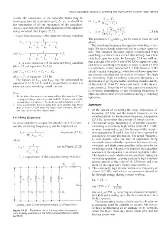
result\. the inductance of the capacitor banks may be
introduced into the total inductance, L2, Le., it should be
the summation of all the reactances of the capacitors
already switched. plus the series reactance of the capacitor
being switched. See Figure 23.22. (23.13)
:. Equivalent reactance of the capacitors already switched
1 The parameters CI,, and bcq are the same as those derived
L,,,, = 1 1 1 above.
-1 + -~ + - + _.. - The switching frequency in capacitor switching is very
L, L, L; L,, high. We have already witnessed this in a single capacitor
I unit. The situation becomes highly complicated when
and L7uq = 1 +k switching is effected in a circuit that already has a few
+ I + +... -~
L, L, L; Ln switched capacitor units. In Example 23.4 we will see
L, = series inductance of the capacitor being switched that a circuit with only 6 out of 60 kVAr capacitor units
(this is L, of equation (23.13)) can have a switching frequency as large a\ over 13 kHz
(in operation, it may not exceed 5-7 kHr because of the
and ('I,,, = C1 + C2 + C? + ... C, circuit's actual impedance), when five of these capacitors
are already switched and the sixth is switched. This high
(this is C, of equation (23.13)) to extremely high switching transient frequency is
The figures of Lzcq and C,,, may be substituted in detrimental in giving rise to the switching inrush currents.
equation (23.13) for L2 and C, respectively to derive a of the order of 15 to 250 times and more, of the steady-
more accurate switching inrush current. state current I,. Since the switching capacitive reactance
is inversely proportional to the switching frequency, it
Nore, Y offers an almost short-circuit condition during a switching
I In the abo\e discussions it is assumed that the capacitor C'? has operation.
no trapped charge when it i\ switched ON. If this is not so. the
current may rise up to 2 . I,,,. as discussed in Section 23.10.1.
2 Field experiment\ have reLealed that such currents may be as Summary
hifh as up to 15-250 times the 5teady st;lte current I,. but will
last onl? up to the first current zero. At the instant of switching the surge impedance, Z,
(equation (23.12)), and the natural frequency of the
Switching frequency switched circuit, i.e. the transient frequency,j; (equation
(23.14)), determines the amount of inrush current.
As discussed above, a capacitor circuit is an L-C circuit, The natural (surge) frequency,,f,. of parallel capacitor
and the switching frequency ,f7 can be expressed as switching is extremely high, of the order of 5-7 kHr
or more. It may not exceed thi.: hecause of the circuit's
(equation (17.1)) own parameters R and L that have been ignored in
our analysis for easy illustration. The actual frequency,
where f,, will depend upon the size of capacitors being
switched compared to the capacitors that were already
1 switched, and their corresponding inductance in the
CC(, = (as in Figure 23.22)
-1 -+ I- switching circuit. A highf, will diminish the capacitive
CI,, C, reactance of the capacitor to an almost negligible value.
C, = capacitance of the capacitor being switched This leads to a near-short-circuit condition during the
switching operation, causing extremely high transient
inrush currents of the order of 15-250 times and even
more of the capacitor's steady-state current I,.
This extremely high inrush current at a frequency of
almost 5-7 kHz will release an enormous amount of
let-through energy during contact making,
i.e. = I,; . t
I
2 x 50
say (250. I, )' . ~
(for an I, of 250. I, occurring at a transient frequency
of 6 kHz and existing up to the Pirst current Lero in a
50 Hz system).
The interrupting device, which may be a breaker or
*L, being L2 and C, (now being switched) is C, of Figure 23.21 a contactor, must be suitable to sustain this energy
without deterioration of or damage to its contacts,
Figure 23.22 Equivalent circuit for R number of capacitor while the fuses must stay intact when provided for
bank already switched on the circuit and another (C,) being backup protection.
switched