Page 800 - Industrial Power Engineering and Applications Handbook
P. 800

231756  Industrial Power Engineering and Applications Handbook

                                                               - 5 x 0.4 + 0.4
                                                                    3x5    pH
                                                        01
                                                        and  C,eq = 9 x 120 + 9x 120 + 9 x 120 + 9 x 120 + 9 x 120
                                                               = 5 x 9 x  120 pF
                                                        or       5 x 9 x  120 x   F

         Figure 23.25  Equivalent circuit for a 60 kVAr bank in star
         made of  3 x 20 kVAr units
                                                                    5 x 9 x  120 x 10-6  x 9 x 120 x 104
                                                                  0.4x6 x10-6(5x9x120x10-6 +9x120x10-6)
         Capacitor normal current for each 60 kVAr bank
                                                              \I'   ~  ~  6  x  9  ~  1  2  0
                                                                2
                                                         =  415   -X   5x9x120x9x120
         Switch  and  HRC fuse  and contactor  rating,  as  in  Section   3x5
         25.6,                                           =  415 x  43750
           = 1.5 x 83.5                                 or  25 414.6 Amps
         or   125.25 A                                  If switching is effected when the incoming capacitor is already
                                                        charged, then the inrush current, I,,,,  will be nearly twice this,
         Thus, for a single capacitor switching of  a 60 kVAr bank, a   i.e.
         rating of  125 A will be required for the switch, fuse and the
         contactor etc.                                 = 25 414.6 x 2
                                                        = 50.80 kA
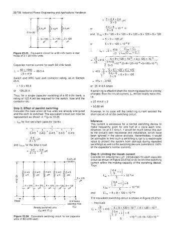
         Step 2:  Effect of parallel switching
         Consider the case when all five units are already energized   However, in no case  will  the  switching  current  exceed  the
         and the sixth is switched. The equivalent circuit can now be   short-circuit  kA of the switching circuit.
         represented as shown in Figure 23.26.
          :.  Le,  for five switched capacitor banks    Inference
                                                        This  current  is excessive  for  a  normal  switching  device  to
                 -              1                       make frequently,  even for  one  half  of  a  cycle  each time.
                                            1
                                      1
                          1   +-   1   +--+   -         However, on an LT circuit, it would be much below this due
                   & + 0.4/3  0.413   0.413   0.413     to the circuit's own resistance and inductance, which  have
                                                        been ignored in the above analysis.  Nevertheless, it would
                    0.4
                 =  -pH                                 be advisable to limit such a switching surge to a reasonable
                   3x5                                  value  to protect  the  system  from  damage  during  repeated
         and L2 eq  for the total circuit               switchings as well as the switching devices (selected at 150%
                                                        of the capacitor's  normal current).
                                                        Step 3: Limiting the inrush current
                                                        Consider an inductance L pH  introduced into each capacitor
                                          0.413 pH      circuit as shown in Figure 23.27(a) or (b) to limit the switching
                                                        current within the  making capacity of  the switching  device.
                                                        Then
                                                                    (?+Lj
                                                                L& =   5    x 104H
                                                9x 120
                                                 PF
                                                                     [y+L)x6
                                                                L;eq  =   5     x 104H
                                                        and     C;eq = 5 x 9 x 120 x 104F

           -1        2      3     4     5      6        The equivalent switching circuit is shown in Figure 23.27(c):
          Steps                            Unit being
              <                         , switched now   :.  Improved
                     Already switched units   ( G)           J2       5 x 9 x  120 x  10-6  x 9 x  120 x 10-6
                        (Lq and Cleq)                    I'  --~415
                                                         m-6        /(e+L)x6
          Figure 23.26  Equivalent switching circuit for six capacitor   IC" '  x10-6x6x9x120x10-6
         units of  60 kVAr each                                           5
   795   796   797   798   799   800   801   802   803   804   805