
Page 804 - Industrial Power Engineering and Applications Handbook
P. 804
23/760 Industrial Power Engineering and Applications Handbook
which will result in an undercompensation by 425 kVAr, or kVAr = kVArl - kVAr,
14.2%. It is therefore advisable to select the voltage rating of
the capacitor units at almost the average voltage of the system, and from Figure 23.29(a)
which in the above case, will be
kVAr,
-- - tan 4
- 33 x 1.075 + 33 x 0.95 = 33.4 kV kW
2
The capacitor banks may be designed for 33.4/ & kV.
See also Example 23.1 to account for the voltage rise due
to series reactor in case series reactors are used. :. kVAr, - kVAr2 = kW(tan $, - tan $?) = kW . K
(23.17)
23.12.2 Determining the kVAr rating where K is a multiplying factor. For quick application of
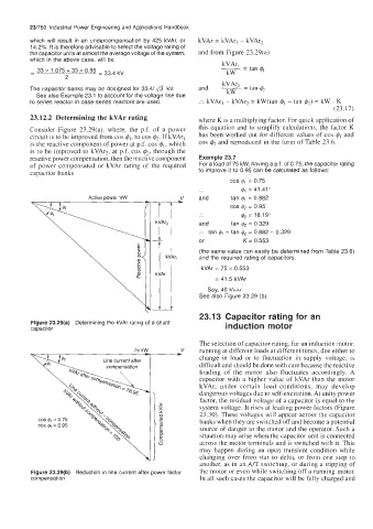
Consider Figure 23.29(a), where, the p.f. of a power this equation and to simplify calculations, the factor K
circuit is to be improved from cos qbl, to cos q&. If kVArl has been worked out for different values of cos #I and
is the reactive component of power at p.f. cos &, which cos & and reproduced in the form of Table 23.6.
is to be improved to kVAr2, at p.f. cos &, through the
reactive power compensation, then the reactive component Example 23.7
of power compensated or kVAr rating of the required For a load of 75 kW, having a p.f. of 0.75, the capacitor rating
capacitor banks to improve it to 0.95 can be calculated as follows:
COS $1 = 0.75
$1 = 41.41"
and tan $1 = 0.882
COS $2 = 0.95
.. & = 18.19"
and tan & = 0.329
:. tan $1 -tan & = 0.882 - 0.329
or K = 0.553
(the same value can easily be determined from Table 23.6)
and the required rating of capacitors,
kVAr = 75 x 0.553
= 41.5 kVAr
Say, 40 kbAr
See also Figure 23.29 (b).
23.13 Capacitor rating for an
Figure 23.29(a) Determining the kVAr rating of a shunt induction motor
capacitor
The selection of capacitor rating, for an induction motor,
75 kW V running at different loads at different times, due either to
c
Line current after change in load or to fluctuation in supply voltage, is
cornwensation difficult and should be done with care because the reactive
loading of the motor also fluctuates accordingly. A
capacitor with a higher value of kVAr than the motor
kVAr, under certain load conditions, may develop
dangerous voltages due to self-excitation. At unity power
factor, the residual voltage of a capacitor is equal to the
system voltage. It rises at leading power factors (Figure
23.30). These voltages will appear across the capacitor
banks when they are switched off and become a potential
source of danger to the motor and the operator. Such a
situation may arise when the capacitor unit is connected
across the motor terminals and is switched with it. This
may happen during an open transient condition while
changing over from star to delta, or from one step to
another, as in an A/T switching, or during a tripping of
Figure 23.29(b) Reduction in line current after power factor the motor or even while switching off a running motor.
compensation In all such cases the capacitor will be fully charged and