
Page 808 - Industrial Power Engineering and Applications Handbook
P. 808
23/764 Industrial Power Engineering and Applications Handbook
r x
ft __
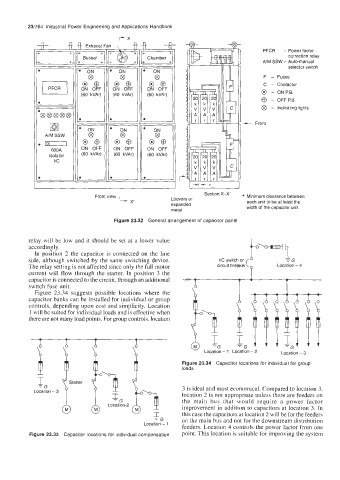
PFCR - Power factor
Chamber correction relay
AfM SSW - Auto-manual
selector switch
F - Fuses
C - Contactor
ON OFF
(60 kVAr) @ - ON P.0.
@ - OFF P.B.
@ - Indicating lights
- Front
ON OFF
(60 kVAr)
r
I Section X-X'
Front view Louvers or * Minimum clearance between
L x each unit to be at least the
expanded width of the capacitor unit.
metal
Figure 23.32 General arrangement of capacitor panel
relay will be low and it should be set at a lower value
accordingly.
In position 2 the capacitor is connected on the line
side, although switched by the same switching device. I/C switch or
The relay setting is not affected since only the full motor circuit breaker( P Location - 4
current will flow through the starter. In position 3 the
capacitor is connected to the circuit, through an additional
switch fuse unit. 0
Figure 23.34 suggests possible locations where the 6 &
capacitor banks can be installed for individual or group 6 e,
controls, depending upon cost and simplicity. Location
1 will be suited for individual loads and is effective when
there are not many load points. For group controls, location - 1 Location l!G\\\lN\
- 'G
Location - 2 Location - 3
Figure 23.34 Capacitor locations for individual for group
loads
3 is ideal and most economical. Compared to location 3,
location 2 is not appropriate unless there are feeders on
the main bus that would require a power factor
improvement in addition to capacitors at location 3. In
I; this case the capacitors at location 2 will be for the feeders
-G on the main bus and not for the downstream distribution
Location - t feeders. Location 4 controls the power factor from one
Figure 23.33 Capacitor locations for individual compensation point. This location is suitable for improving the system