
Page 809 - Industrial Power Engineering and Applications Handbook
P. 809
Power capacitors: behaviour, switching and improvement of power factor 23/765
power factor, reducing the kVA demand and the strains From main PCC
on the main supply and distribution network. Technically
speaking, it has no advantages for in-plant power
distribution, nor does it help to reduce the kVA strain on l/C breaker
the feeding cables or the loading on the power distribution
feeders. But for simplicity and ease of control for the To PFCR
entire plant it is used most often.
23.15 Automatic PF correction of a
system
As discussed above, for an industrial or power plant
application or an installation with a number of inductive
load points a grvup capacitor control is always more
effective. simple and economical. Such an installation
generally has a frequent variation in its load demand due
to some feeders coming on the bus and some falling out
at different times. There may be variation in the individual
feeder’s load demand, such as a tool room, where not all
the machines will be working at a time, or a pulp mill
and paper mill, where the paper mill has a continuous
load, the pulp mill an intermillent one. A water treatment
plant or a pump house are similar installations where all
or some of the loads would be in operation at a time. For
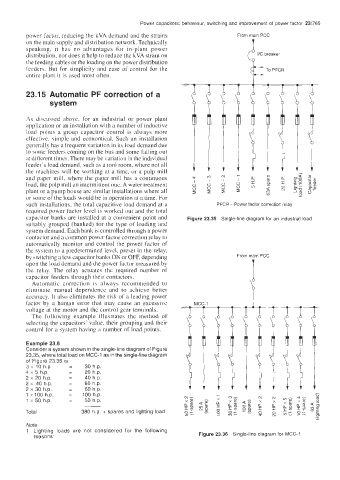
such installations. the total capacitive load demand at a PFCR - Power factor correction relay
required power factor level is worked out and the total
capacitor banks are installed at a convenient point and Figure 23.35 Single-line diagram for an industrial load
suitably grouped (banked) for the type of loading and
system demand. Each bank is controlled through a power
contactor and a common power Lactor correction relay to
automatically monitor and control the power factor of
the system to a predetermined level, preset in the relay,
by witching a few capacitor banks ON or OFF, depending From main PCC
upon the load demand and the power factor irieasured by i
the relay. The relay actuates the required number of
capacitor feeders through their contactors.
Automatic correction is always recommended to
eliminate manual dependence and to achieve better
accuracy. It also eliminates the risk of a leading power
factor by a human error that may cause an excessive
voltage at the motor and the control gear terminals.
The following example illustrates the method of
selecting the capacitors’ value, their grouping and their
control for a system having a number of load points.
Example 23.8
Consider a system shown in the single-line diagram of Figure
23.35, where total load on MCC-1 as in the single-line diagram
of Figure 23.36 is
3 x 10 h.p = 30 h.p.
4 x 5 h.p. = 20 h.p.
2 x 20 h.p. = 40 h.p.
2 x 40 h.p. = 80 h.p.
2 x 30 h.p. = 60 h.p.
1 ~100 h.p. = 100 h.p.
1 x 50 h.p. = 50 h.p.
__
Total 380 h.p. + spares and lighting load
Note
1 Lighting loads are not considered for the following
reasons: Figure 23.36 Single-line diagram for MCC-1