
Page 814 - Industrial Power Engineering and Applications Handbook
P. 814
Power capacitors: behaviour, switching and improvement of power factor 23l769
A good relay can be modified to perform a particular be switched again. This delay can be eliminated with
switching sequence during ON and OFF and both the use of special discharge devices, which would
sequences need not be same. The following is a type of make it possible to achieve fast switching. Timers
relay that can be modified to perform any desired switching may be introduced into the switching circuit to allow
pattern. for the thus reduced discharge time between two
consecutive switchings.
23.16.7 Binary switching 2 A six-stage binary Now the capacitors are arranged
in the ratio of 1 : 2 : 4 : 8 : 16 : 32 units, i.e. a six-stage
This is a highly recommended method of capacitor capacitor bank can be switched in 63 steps, with
switching for installations that are large and require very different switching combinations, at a difference of
fine monitoring and correction of p.f. with the smallest just one unit. If the smallest unit is of 5 kVAr, a total
number of banks. The entire reactive requirement is correction of 3 15 kVAr is possible in steps of 5 kVAr
arranged in only a few steps yet a small correction up to each with just six sets of capacitor units and banks in
the smallest capacitor unit is possible. The relay is the ratio of 5 : 10 : 20 : 40 : 80 : 160 kVAr. The rest of
sequenced so that through its binary counter the required the sequencing is the same, as illustrated for four-
switching is achieved in small steps, with just four or six stage binary. The six-stage sequencing scheme can
sets of capacitor units or banks. The operation of the be developed along similar lines to those in Table 23.9.
entire sequence can be illustrated as follows:
A six-stage binary scheme should normally be adequate
1 A four-stage binary The capacitor units or banks to switch even very large banks. Yet this sequencing can
are arranged in the ratio 1 : 2 : 4 : 8. The four-stage be further modified to achieve a more particular sequencing
capacitor bank is switched in one to fifteen steps pattern when required, as noted below.
(summation of 1 + 2 + 4 + 8), giving fifteen different
values of reactive power control in small steps of one 23.16.8 Modified binary switching
unit each. To achieve this, the relay goes up and down
only one step at a time. For example, if we have to A fifteen- or sixty-three-step switching, as noted above,
switch 75 kVAr in small steps, this can be arranged in may be cumbersome and require too large a time gap to
the ratio of 5 : 10 : 20 : 40 kVAr units. These capacitors switch. Switchings in such small steps may indeed not
can be switched in steps of 5 kVAr each (total 15 be necessary. It is possible to modify the sequencing of
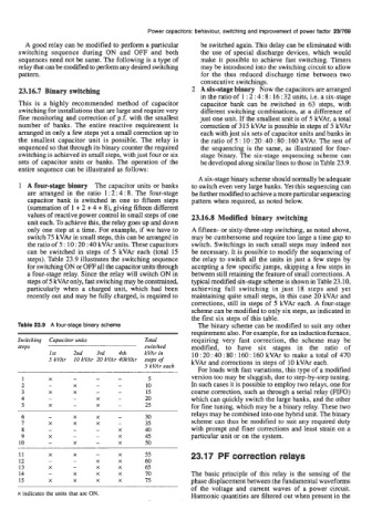
steps). Table 23.9 illustrates the switching sequence the relay to switch all the units in just a few steps by
for switching ON or OFF all the capacitor units through accepting a few specific jumps, skipping a few steps in
a four-stage relay. Since the relay will switch ON in between still retaining the feature of small corrections. A
steps of 5 kVAr only, fast switching may be constrained, typical modified six-stage scheme is shown in Table 23.10,
particularly when a charged unit, which had been achieving full switching in just 18 steps and yet
recently out and may be fully charged, is required to maintaining quite small steps, in this case 20 kVAr and
corrections, still in steps of 5 kVAr each. A four-stage
scheme can be modified to only six steps, as indicated in
the first six steps of this table.
Table 23.9 A four-stage binary scheme The binary scheme can be modified to suit any other
requirement also. For example, for an induction furnace,
Switching Capacitor units Total requiring very fast correction, the scheme may be
steps switched modified, to have six stages in the ratio of
1st 2nd 3rd 4th kVAr in 10 : 20 : 40 : 80 : 160 : 160 kVAr to make a total of 470
5 kVAr 10 kVAr 20 kVAr 4OkVAr steps of kVAr and corrections in steps of 10 kVAr each.
5 kVAr each
For loads with fast variations, this type of a modified
version too may be sluggish, due to step-by-step tuning.
In such cases it is possible to employ two relays, one for
coarse correction, such as through a serial relay (FIFO)
which can quickly switch the large banks, and the other
for fine tuning, which may be a binary relay. These two
6 - X X - 30 relays may be combined into one hybrid unit. The binary
7 X X X - 35 scheme can thus be modified to suit any required duty
8 - - - X 40 with prompt ad finer corrections and least strain on a
9 X - - X 45 particular unit or on the system.
10 - X - X 50
11 X X - X 55 23.17 PF correction relays
12 - - X X 60
13 X - X X 65
14 - X X X 70 The basic principle of this relay is the sensing of the
15 X X X X 75 phase displacement between the fundamental waveforms
of the voltage and current waves of a power circuit.
x indicates the units that are ON. Harmonic quantities are filtered out when present in the