
Page 815 - Industrial Power Engineering and Applications Handbook
P. 815
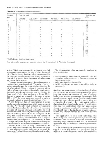
Switching   Capacitor bank                                                     Total switched
        steps                                                                          kVAr
                    1st 5 kVAr   2nd  10 kVAr   3rd 20kVAr   4th 40kVAr   5th 80 kVAr   6th 160 kVAr
                                          ~~~
                                                                                        5
                                                                                        10
                                                                                        15
                                                                                        35
                                                                                       55
                                                                                       75
                                                                                        95
                                                                                       1 15
                                                                                       135
                                                                                       155
                                                                                       175
                                                                                       195

         43                                         X         -                        215
         47                                         X         -                        235
         51                                         -         X                        255
         55                                         -         X                        215
         59                                         X         X                        295
         63                                         X         X                        315
        *Modified binary for a four-stage scheme
        Note: It is possible to achieve any correction  within a step of one unit only (5 kVAr in the above case).


        system. This is a universal practice to measure the p.f. of   The p.f.  correction  relays  are  normally  available  in
        a system to economize on  the cost of relay. The actual   three versions, i.e.
        p.f. of the circuit may therefore be less than measured by
        the relay. But one can set the relay slightly higher (less   Electromagnetic  (being  quickly  outdated). They  are
        than unity), to account for the harmonics, when harmonics   very slow, and may take up to 2 minutes or more to
        are present in the system.                       initiate a correction.
          From this phase displacement, a d.c. voltage output is   Solid state-based on discrete ICs.
        produced by  a transducer circuit. The value of  the d.c.   Solid  state-based  on  micro-controllers  (micro-
        voltage  depends  upon  the phase  displacement, Le. the   processors).
        p.f. of the circuit. This d.c. voltage is compared with a
        built-in reference d.c. voltage, adjustable by the p.f. setting   A delayed correction may not be desirable in applications
        knob or by selecting the operating band provided on the   that have a fast variation of loads such as rolling mills,
        front  panel  of  the  relay,  as  shown  in  Figure  23.38.   induction  furnaces,  arc  furnaces,  all  types  of  welding
        Corrective signals are produced  by the relay to  switch   loads, power presses, hammers and elevators etc. Such
        ON  or  OFF the  stage  capacitors  through  a  built-in   type of loads draw reactive power from the supply source.
        sequencing circuit to reach the desired level of p.f.   Since  the  loads  change  rapidly,  unless  they  are
          A  little  lower p.f.  than  set  would  attempt  to  switch   compensated  promptly  they  may  cause  voltage
        another unit or bank of capacitors, which may overcorrect   fluctuations, low p.f. and high harmonics. A rapid voltage
        the set p.f. Now the relay would switch off a few capacitor   drop may even trip the load, which may cause serious
        units or banks to readjust the p.f. and so will commence   damage to machines in operation. For instance, in a rolling
        a process  of  hunting,  which  is  undesirable.  To  avoid   mill, the mill may be damaged as the process ingots may
        such a situation the sensitivity of the comparator is made   be  half-way  through  between  the  rolls  when  the  mill
        adjustable through  the  knob  on  the  front  panel  of  the   stopped.
        relay.  The sensitivity  control  can  be  built  in  terms  of   With  application  of  solid-state  technology,  this
        phase angle (normally adjustable from 4 to  14 degrees   shortcoming of an electromagnetic relay is automatically
        electrical) or percentage kVAr. Thc sensitivity, in terms   overcome.  The  solid-state  relays  are  available with
        of an operating band, helps the relay to avoid a marginal   switching stages as many as from  2 to  16. For  special
        overcorrection or undercorrection and hence the hunting.   applications, they can be designed for even higher numbers
          As soon as the system’s actual p.f. deviates from the   of  steps.
        pre-set limits, the relay becomes activated and switches   A time delay is built in to allow discharge of a charged
        in or switches out capacitor units one by  one, until  the   capacitor  up  to  90% before  it  is  reswitched.  This  is
        corrected p.f. falls within the sensitivity limit of the relay.   achieved by introducing a timer into the relay’s switching