
Page 817 - Industrial Power Engineering and Applications Handbook
P. 817
23/772 Industrial Power Engineering and Applications Handbook
1 unbalance if any, by measuring the kVAr in each phase
and provide an^ appropriate signal."
( 0 At the start of the correction cycle the relay calculates
the required kVAr, examines the available capacitor
values stored in its memory, takes a decision to switch
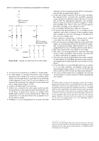
CT to monitor ON or OFF the appropriate capacitors and switches
system p.f. them in rapid succession to reach the target p-f. in the
least possible time. Now it uses the CTs provided in
the main incoming circuit (Figure 23.39).
It can identify the next ideal unit for switching.
To achieve the desired level of p.f. it switches on the
capacitor unit which is nearest to the required rating
and available for the next switching or switches off a
few units in a similar way.
Each capacitor circuit has a software timer which
reswitches the unit only when it has timed out.
CT to monitor It is not necessary to arrange capacitors in any particular
capacitor health
order, nor of particular ratings for the different stages.
But, as mentioned earlier, when desired it can also be
programmed for any switching scheme noted above.
The units need not be very small or very large.
The relay can be programmed to store the operating
history of the cumulative service hours for each unit
to obtain uniformity in ageing of each unit.
The relay can also be programmed to provide a counter
for the number of switching operations each capacitor
Figure 23.39 Location of monitoring CTs for static relays has already performed on per day, per month or yearly
bases."
Since the relay is connected in the same way as a meter
is, it can read, calculate, and display all the desired
operating parameters such as, V, l,L p.f., kVAr, kW, and
kVA as well as kWh, kVArh and maximum demand.*
As soon as it is switched on, it shifts to a 'learn mode'. The relay can be connected to a computer and transmit
In 'learn mode', it measures the kVAr value of each all such data to a remote station for further monitoring
capacitor unit in terms of C in pF by switching them and control.
one by one through the CTs provided in the incoming
of the capacitor circuit. The CTs are provided so as to Note
measure the current of the capacitor circuit alone and To ensure proper sensing of the incoming current and its phase
not of other loads (Figure 23.39). displacement by the relay it is essential that the CTs ratio and their
It stores all these data in its memory. VA burden chosen for the required duty are close to the actual
After every correction the relay again carries out the requirement as noted in Table 15.8. Sometimes this fact is overlooked
measurements on the capacitor units (periodically, say, and CTs with a much higher VA burden or ratio or both are chosen
in 24 hours in supervisory mode), to monitor their while the secondary circuit may not be adequately loaded. In this
health and to detect for any deterioration. When the case the CTs may not accurately transform the primary parameters
to the secondary and, in turn, the relay may not send accurate
capacitance of a unit falls below the acceptable level signals. Moreover, the relay itself may operate only at minimum
it can emit an alarm. 1% or more of its rated current (1 or 5 A), depending upon its
Similarly it can be programmed to measure the load design and type (IEC 60051-1).
*These are special features that can be built into the relay. But each
may involve an element of cost and the relay manufacturers may
therefore provide only the essential features as standard and the
remaining ones on request.