Page 819 - Industrial Power Engineering and Applications Handbook
P. 819
23/774 Industrial  Power Engineering and Applications Handbook

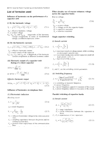
        List of  formulae used                         Filter circuits: use of reactor enhances voltage
                                                       across the capacitor hanks
        Influence of harmonics on the performance of a   Rise in voltage,
        capacitor unit
                                                                                             (23.8)
        (i) By the harmonic voltage
                                                        Vph = system voltage
         v,  =1/(v,2+v;+v;+v;+...v;")          (13.1)   Vc = voltage across the capacitor banks
                                                        Xc = capacitive reactance
         V, = effective harmonic voltage                XL = inductive reactance
         VI = system voltage
         V,,,  V,,,  V,,  and  V,,  etc,  = magnitudes  of the harmonic
             voltage  components  in  terms  of  fundamental   Single-capacitor switching
             voltage.  at different harmonic orders
                                                       (i) Inrush current
        (ii) By the harmonic currents                   I,,  = I,( 1 + F)

         I,,  =,/(I:+  91:h3  + 251:h,+  491:,,,+  ... n2 I&)  (23.2)                        (23.9)
         I,,  = effective harmonic current              I,  = maximum inrush or making current, while switching
          I, = rated current of the capacitor               an unchanged capacitor unit.
            Ich5, I,,,  and ILhn ctc. = magnitude of the harmonic   I, = maximum stead  -state current (capacitor peak full
              current components at different harmonic orders   load current  (&Ic  ))
                                                        Isc  = fault level  of the system
         (iii) Harmonic output of a capacitor unit
            Rating of a shunt capacitor
                                                                                            (23.10)
                43. v'
         kVAr =                                (23.3)
                1000 ' X'                              L, and C, are the switching circuit parameters
                  &.V'.2?rf.c
         or  kVAr =                            (23.4)   (ii) Switching frequency
                       IO00                                  i;'-=f.F
        Effective harmonic output                             (Short  circuit  kVA)          (23.11)
                                                       ''   =f  (Capacitor kVAr)   XL
                                                        .f, = switching or transient frequency
                                               (23.5)   f = powcr frequency
                                                       X, = power frequency capacitive reactance of the circuit
                                                       X, = power frequency inductive reactance of the circuit
         Influence of harmonics on telephone lines
         (I) Electrostatic induction                   Parallel switching of capacitor banks
         Blockirig  circuit
                                                       (i) Inrush current
                 1                             (23.6)
            = 2n.
                                                                                             (23.12)
         ,fh  = notch frequency
                                                           Z, = surge impedance
                                               (23.7)      L2 = circuit  inductance  between  the  capacitors  in
                                                               henry
          V,  = induced electrostatic voltage in the Communication   C,, C2 = capacitances of two capacitors
              lines
                                                                    c, ' c2
         C, = coupling capacitance between the power and the   =  JG                         (23.13)
              communication lines
         Cg = ground circuit capacitance of the communication
              lines

