
Page 824 - Industrial Power Engineering and Applications Handbook
P. 824
System voltage regulation 241779
24.1 Capacitors for improvement of
system voltage regulation
Another important application of capacitors is to improve
the voltage regulation of a power supply system. The Transmitting-side
regulation of a power system at the receiving end is voltage E,
defined by
Regulation 1 I- Primary
transmission
- Voltage at no load - Voltage at full load x 100 1 I (Generator side)
-
Voltage at no load ~ I
(24. I) Series capacitors
Higher regulation will mean a higher voltage fluctuation !-
Receiving-end
at the receiving cnd, resulting in poor stability of the voltage E,
system. Regulation up to 3-5% may be considered
satisfactory. To improve the regulation of a system, power Secondary
capacitors can be used in series at the receiving end of transmission
the \ystem. ~~ (Load side)
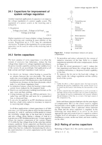
Figure 24.1 A simple transmission network with series
24.2 Series capacitors compensation
1 To neutralize and reduce substantially the content of
The basic purpose of series capacitance is to offset the inductive reactance of the line. Refer to a simple
content of excessive line inductance, reduce the line transmission network with series compensation. shown
voltage drop, improve its voltage regulation and enhance in Figure 24.1.
the power transfer capability and hence the stability level 2 To alter the circuit parameters L and C, reduce the
of the system. It can accordingly find application at all line impedance and hence the voltage drop, and also
high-current and high-impedance loads such as to enhance utilization. i.e. the power transfer capability
ofthe line.
An electric arc furnace. where heating is caused by 3 To improve the far end or the load-side voltage. in
arc plasma between the two electrodes. The arcing other words, the voltage regulation and the stability
makes the circuit highly inductive, besides generating level of the I;ystem.
unbalanced currents (third harmonics), due to different
touchdown arc distances in the three electrodes which Notes
make it a non-linear impedance load. Unlike the above, a \hunt capacitor alterh the load currcnt by
An induction furnace, where the heating is due to eddy offsetting the reactive coinponcnt of thc current (Figure 23.2)
current losses induced by the magnetic field. hy improving the load p.fand altering the characteristics of the
load.
Electric arc and resistance welding transformers as for A series capacitor has little application it1 an LT system due to
spot. seam and butt welding. the high content of line resi\tance and bery little of inductance.
A long transmission line, say, 400 km and more. for a Any amount of reactive compensation will scarcely influence
radial line and 800 km and more for a symmetrical the performance of the line, a\ a rerult of the high content ill
line, as discussed later. IR. compared to IX,.
It can also be applied to an HT distribution network
that has ii high series inductive reactance to improve Series and shunt cauacitors both urovide the same degree
c
its receiving-end voltage. of compensation. But it is the correct reactive support
that provides a more stable system less prone to load and
voltage fluctuations. Thus a judicious choice between
In all these applications a shunt capacitance is of little
relevance. as it will not be able to offset the line inductive the shunt and the series capacitors is required. In the
following our main thrust is to arrive at the most
reactance, X,, with X,, and hence will be unable to contain
the switching voltage dips at the load end in furnaces appropriate type and extent of reactive support to achieve
a higher level of utilization of a power transmission or
and also voltage drops during a change of load in a distribution system, on the one hand. and more stability,
transmission or HT distribution network. A shunt capacitor on the other.
offsets the reactive component of the current (Figure
23.2) while the line voltage drop, for the same line current,
remains unaltered. Series capacitors are therefore more 24.3 Rating of series capacitors
appropriate where voltage regulation is the main criterion,
rather than line loss reduction. Summarizing the above, Referring to Figure 24.2. thi4 can be expres4ed by
the main functions of a series capacitance can be stated
as follows: kVAr=3 I,’ X, (24 3)