
Page 825 - Industrial Power Engineering and Applications Handbook
P. 825
24/780 Industrial Power Engineering and Applications Handbook
GT kVAr
x, = 1000'~
t Load side 31
E, Line Series E, c= 31'
1000 . kVAr. 2d
parameters capacitors kVar = 3$ rating of the series capacitors
1 = Rated current of series capacitors
Figure 24.2 The single-line diagram for Figure 24.1
where the line voltage, they are insulated from the ground and
I, = line current. The value of line current to be from each phase according to the system voltage. For
considered for calculating the size of capacitor banks this purpose, they are generally mounted on individual
must take account of the likely maximum load platforms for each phase, which are adequately insulated
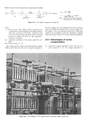
variation during normal operation or the overload from the ground. Figure 24.3 shows such an installation.
protection scheme provided for the capacitors,
whichever is higher.
X, = capacitive reactance of the series capacitors per 24.4 Advantages Of series
phase. corn pensat ion
and voltage rating = I, . X,.
This rating will be much less than the nominal voltage (i) Automatic voltage regulation: Since the VAr of a
of the system. But since the series capacitors operate at series capacitor 0~ I;, the voltage regulation is
Figure 24.3 The installation of HT capacitor banks (Courtesy: Khatau Junker Ltd)