
Page 827 - Industrial Power Engineering and Applications Handbook
P. 827
24/782 Industrial Power Engineering and Applications Handbook
I, (fault)
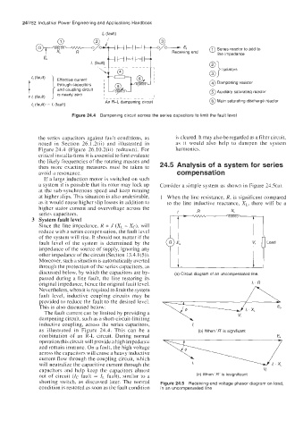
@ Series reactor to add to
E,
iving end line impedance
0) Isolators
0
@ Dampening resistor
@ Auxiliary saturating reactor
An R-L dampening circuit @ Main saturating discharge reactor
lC (fault) = I, (fault)
Figure 24.4 Dampening circuit across the series capacitors to limit the fault level
the series capacitors against fault conditions, as is cleared. It may also be regarded as a filter circuit,
noted in Section 26.1.2(ii) and illustrated in as it would also help to dampen the system
Figure 24.4 (Figure 26.10.2(ii) redrawn). For harmonics.
critical installa-tions it is essential to first evaluate
the likely frequencies of the rotating masses and
then more exacting measures must be taken to 24.5 Analysis of a system for series
avoid a resonance. compensation
If a large induction motor is switched on such
a system it is possible that its rotor may lock up Consider a simple system as shown in Figure 24.S(a).
at the sub-synchronous speed and keep running
at higher slips. This situation is also undesirable, 1 When the line resistance, R, is significant compared
as it would cause higher slip losses in addition to to the line inductive reactance, X,, there will be a
higher stator current and overvoltage across the
series capacitors.
3 System fault level
Since the line impedance, R + J (X, - Xc), will
reduce with a series compensation, the fault level
of the system will rise. It should not matter if the !C
fault level of the system is determined by the V, Load
impedance of the source of supply, ignoring any
other impedance of the circuit (Section 13.4.1(5)).
Moreover, such a situation is automatically averted
through the protection of the series capacitors, as
discussed below, by which the capacitors are by- (a) Circuit diagram of an uncompensated line.
passed during a line fault, the line restoring its
original impedance, hence the original fault level. I, . R
Nevertheless, when it is required to limit the system
fault level, inductive coupling circuits may be
provided to reduce the fault to the desired level.
This is also discussed below:
The fault current can be limited by providing a
dampening circuit, such as a short-circuit-limiting
inductive coupling, across the series capacitors,
as illusti-ated in Figure 24.4. This can be a (b) When 'R' is significant
combination of an R-L circuit. During normal E,
operation this circuit will provide a high impedance
and remain immune. On a fault, the high voltage
across thc capacitors will cause a heavy inductive
current flow through the coupling circuit, which
will neutralize the capacitive current through the
capacitors and help keep the capacitors almost V,
out of circuit (Zc fault = I, fault), similar tu a (c) When 'R' is insignificant
shorting switch, as discussed later. The normal Figure 24.5 Receiving-end voltage phasor diagram on load,
condition is restored as soon as the fault condition in an uncompensated line