
Page 831 - Industrial Power Engineering and Applications Handbook
P. 831
24/786 Industrial Power Engineering and Applications Handbook
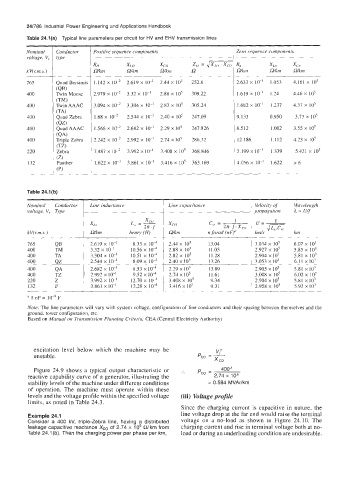
Table 24.l(a) Typical line parameters per circuit for HV and EHV transmission lines
Nominal Conductor Positive sequence components Zero wquence components
voltage, V, type __
Ro XLO XCO Zo = JzzG Rn XLn XC,
kV(zm.s.) Wkm n/km Wkm R n/km Wkm GWcm
__
765 Quad Bersimib 1.142 x 2.619 x IO-' 2.44 x 10' 252.8 2.633 x IO-' 1.053 4.161 x lo5
1 (QB)
400 Twin Moose 2.979 x IO-* 3.32 x IO-' 2.88 x IO5 309.22 1.619 x IO-' 1.24 4.46 x io5
(TM)
400 Twin AAAC 3.094 x 3.304 x IO-' 2.82 x IO5 305.24 1.682 x lo-' 1.237 4.37 x 10'
(TA)
400 Quad Zebra 1.68 x 2.544 x IO-' 2.40 x IO5 247.09 9.133 0.950 3.73 x 10⁵
(QZ)
400 Quad AAAC 1.566 x 2.682 x IO-' 2.29 x 10⁵ 247.826 8.512 1.002 3.55 x io5
(QA)
400 Triple Zebra 2.242 x 2.992 x IO-' 2.74 x IO' 286.32 12.186 1.112 4.23 x 10⁵
(TZ)
220 Zebra 7.487 x 3.992 x IO-' 3.408 x io5 368.846 2.199 x IO-' 1.339 5.421 x IO5
132 1.622 x IO-' 3.861 x IO-' 3.416 x IO' 363. I69 4.056 x IO-' 1.622 26
___ -. ____
Table 24.l(b)
~~~~~
Nominal Conductor Line inductance Line capacitance Wavelength
voltage, V, Tvpe
1
x LO
XL" L,, = - xc, Ci, = 27r. f . x,, u=- 1
2n. f
kV(zm.s.) GWcm henry (H) Wkm n farad (nF)' kds krn
____ __--
765 QB 2.619 x IO-' 8.33 x IO4 2.44 x 10⁵ 13.04 3.034 X IO5 6.07 x IO?
400 TM 3.32 x IO-' 10.56 x IO4 2.88 x Io" 1 1.05 2.927 x 10' 5.85 x 10'
400 TA 3.304 x IO-' 10.51 x IO1 2.82 x io5 11.28 2.904 x io5 5.81 x 10'
400 QZ 2.544 x IO-' 8.09 x IO4 2.40 x IO5 13.26 3.053 x IO5 6.11 xi03
400 QA 2.682 x IO-' 8.53 x IO4 2.29 x 10' 13.89 2.905 x Io" 5.81 x IO'
400 TZ 2.992 x lo-' 9.52 x IO4 2.74 x IO' 11.61 3.008 x Io" 6.02 x 10'
220 Z 3.992 x IO-' 12.70 x 10" 3.408 x io5 9.34 2.904 X 10' 5.81 X IO3
132 P 3.861 x IO-' 12.28 x 10" 3.416 x 10⁵ 9.3 1 , 2.958 x IO5 5.92 x10'
* I nF = IO-' F
Note: The line parameters will vary with system voltage, configuration of line conductors and their spacing between themselves and the
ground, tower configuration, etc.
Based on Manual on Transmission Planning Criteria, CEA (Central Electricity Authority)
excitation level below which the machine may be ":
unstable. fco = -
x co
Figure 24.9 shows a typical output characteristic or Pco = 400
reactive capability curve of a generator, illustrating the 2.74 x 10⁵
stability levels of the machine under different conditions = 0.584 MVArIkm
of operation. The machine must operate within these
levels and the voltage profile within the specified voltage (iii) Voltage profile
limits, as noted in Table 24.3.
Since the charging current is capacitive in nature, the
Example 24.1 line voltage drop at the far end would raise the terminal
Consider a 400 kV, triple-Zebra line, having a distributed voltage on a no-load as shown in Figure 24.10. The
leakage capacitive reactance Xc0 of 2.74 x lo5 Wkm from charging current and rise in terminal voltage both at no-
Table 24.l(b). Then the charging power per phase per km, load or during an underloading condition are undesirable.