
Page 836 - Industrial Power Engineering and Applications Handbook
P. 836
24/790 Industrial Power Engineering and Applications Handbook
= L0.2Zf. E,
1
= X,, i.e. the inductive reactance of the entire
line length.
and equation (24.3) will become
E, E,
p=-. sin 6 (24.4)
XL
For short lines, this is a very useful formula.
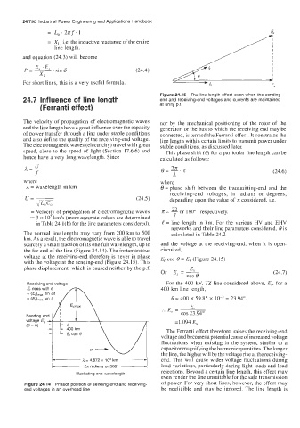
Figure 24.15 The line length effect even when the sending-
24.7 Influence of line length end and receiving-end voltages and currents are maintained
(Ferranti effect) at unity p.f.
The velocity of propagation of electromagnetic waves nor by the mechanical positioning of the rotor of the
and the line length have a great influence over the capacity generator, or the bus to which the receiving end may be
of power transfer through a line under stable conditions connected, is termed the Ferranti effect. It constrains the
and also define the quality of the receiving-end voltage. line lcngth within certain limits to transmit power under
The electromagnetic waves (electricity) travel with great stable conditions, as discussed later.
speed, close to the speed of light (Section 17.6.6) and This phase shift (6) for a particular line length can be
hence have a very long wavelength. Since calculated as follows:
U
(24.6)
where where
= wavelength in km 8 = phase shift between the transmitting-end and the
u=- 1 (24.5) receiving-end voltages, in radians or degrees,
depending upon the value of z considered, i.e.
JL,c,
22
= Velocity of propagation of electromagnetic waves z = - or 180" respectively.
7
-- 3 x IOs km/s (more accurate values are determined
in Table 24.1 (b) for the line parameters considered). e = line length in km. For the various HV and EHV
networks and their line parameters considered, 6 is
The normal line lengths may vary from 200 km to 500 calculated in Table 24.2
km. As a result, the electromagnetic wave is able to travel
scarcely a small fraction of its one full wavelength, up to and the voltage at the receiving-end, when it is open-
the far end of the line (Figure 24.14). The instantaneous circuited,
voltage at the receiving-end therefore is never in phase E, cos 6 = E, (Figure 24.15)
with the voltage at the sending-end (Figure 24.15). This
phase displacement, which is caused neither by the p.f. E,
Or E, = - (24.7)
cos 6
Receiving end voltage For the 400 kV, TZ line considered above, Er, for a
E, rises with 6' 400 km line length,
= (E,),,, sin wt
= sin 8 6 = 400 x 59.85 x lo-' = 23.94".
Sending eni/L e I \, :. E, = cos 23.94"
E,
voltage E, = 1.094 E,
(e= 0)
400 km The Ferranti effect therefore, raises the receiving-end
E, cos 8 Q- UI
voltage and becomes a potential cause of increased voltage
~
fluctuations when existing in the system, similar to a
:
capacitor magnifying the harmonic quantities. The longer
the line, the higher will be the voltage rise at the receiving-
end. This will cause wider voltage fluctuations during
A = 4.872 x lo3 krn
load variations, particularly during light loads and load
radians
or
360"
2n
Illustrating one wavelength rejections. Beyond a certain line length, this effect may
even render the line unsuitable for the safe transmission
Figure 24.14 Phasor position of sending-end and receiving- of power. For very short lines, however, the effect may
end voltages in an overhead line be negligible and may be ignored. The line length is