
Page 840 - Industrial Power Engineering and Applications Handbook
P. 840
24/794 Industrial Power Engineering and Applications Handbook
@ Uncompensated
@ Partially compensated
@ Fully compensated
(PIP,) -
I
Natural load
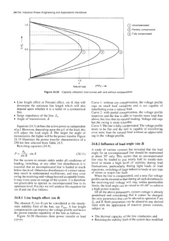
Figure 24.20 Capacity utilization load curves with and without compensation
Line length effect or Ferranti effect, sin 8, that will Curve 1 : without any compensation, the voltage profile
determine the optimum line length which will also sags on small load variations and is not capable of
depend upon whether it is a radial or a symmetrical transferring even a natural load.
line. Curve 2: with partial compensation, the voltage profile
Surge impedance of the line, Z,. improves and the line is able to transfer more load than
Angle of transmission, 6. above, but less than its natural loading. Voltage still sags
but the swing is more tolerable.
Equation (24.3) defines the active power as independent Curve 3: The line is fully compensated. The voltage profile
of p.f. However, depending upon the p.f. of the load, this tends to be flat and the line is capable of transferring
will adjust the load angle 6. The larger the angle of even morc than the natural load without an appreciable
transmission, the higher will be the power transfer. Figure sag in the voltage profile.
24.19 illustrates the power transfer characteristics of a
250 km line selected from Table 24.5. 24.8.2 Influence of load angle (sin 8)
Rewriting equation (24.9),
A study of various systems has revealed that the load
Po
P = -.sin 6 (24.1 1) angle for an uncompensated line should be maintained
sin 8 at about 30" only. This means that an uncompensated
For the system to remain stable under all conditions of line may be loaded to just nearly half its steady-state
loading, switching, or any other line disturbances it is level to retain a high level of stability during load
essential that an uncompensated line is loaded at much fluctuations, particularly during light loads or load
below this level. Otherwise disturbances of a minor nature rejections, switching of large inductive loads or any type
may result in undampened oscillations, and may even of minor or major line fault.
swing the receiving-end voltage beyond acceptable limits. When the line is compensated, and a near-flat voltage
It may even cause an outage of the system. It is therefore profile can be ensured so that during all such disturbances
not practicable to operate an uncompensated line to its the receiving-end voltage will stay within permissible
optimum level. For this we will analyse this equation for limits, the load angle can be raised to 45-60" 10 achieve
sin 0 and sin 6 as follows. a high power transfer.
Of all the above parameters, system voltage is already
predefined and considering that it cannot be changed,
24.8.1 Line length effect (sin e) the only parameters that can be altered to optimize P are
Z, and 0. Both parameters can be altered to any desired
The element Polsin 0 can be considered as the steady- limit with the application of reactive power controls,
state stability limit of the line, say P,,,. A line length subject to
compensation can improve the voltage profile and hence
the power transfer capability of the line as follows.
Figure 24.20 illustrates three power transfer or load The thermal capacity of the line conductors and
curves: Retaining the stability limit of the system thus modified.