
Page 845 - Industrial Power Engineering and Applications Handbook
P. 845
System voltage regulation 24/799
conditions, and the remainder are switched. Moreover, Note
switchable reactors are switched only during a On 66 kV networks the MVAr loading is normally high and
temporary disturbance, therefore they have no adverse therefore one practice is to install MVAr meters and adopt a
effect on Po. Ideally they can be made fixed to manual switching during variation of MVAr beyond the
compensate 50-60% of C, and the remainder switched permissible level, purely as a cost consideration.
in a few steps. The size and number of steps will
depend upon the likely underloading, open-circuiting 3 Series capacitors These are used for line length
during offpeak periods or other temporary disturbances. compensation to help transmit power over long
The overvoltages that may occur under such conditions, distances and also improve the stability level of the
and which must be controlled through these reactors, network. They are usually installed at the line ends or
is a matter of system design practice adopted by a at the selected locations. They reduce Zo and enhance
country or its central power authorities and may be SIL, PO, and boost the receiving-end voltage.
broadly based on our discussions in Section 24.6 and
Table 24.3. To determine more accurate overvoltage Example 24.3 Application of series compensation on
conditions, however, a TNA or EMTP study would an HT distribution network
be better for an existing system and earlier data and Let us consider the primary distribution network of Example
23.2 as shown in Figure 24.25(a) feeding an LT load of 29.4
experience for a new system. MW at 0.98 p.f. through a 33/0.4 kV transformer. The following
line parameters have been considered:
Note Resistance of primary distribution overhead lines, section
On 132 kV networks the MVAr loading is light. as most of the B-B at the operating temperature,
p.F. is controlled at the distribution level and the capacitive
chargiiig MVAr demand is low (Table 24.2, column 9). The Ro = 0.13 akm per phase
charging MVAr is normally not compensated because, on load, Inductive reactance of this section at 50 Hz
more than this is offw by the load p.f.
XLo = 0.4 akrn per phase
Shunt capacitors These are used to supplement the There is no leakage capacitance, C,, and hence no Ferranti
natural line capacitance, C,, under heavy inductive effect on such low voltages. We will use series compensation
loading depending upon the system voltage, but are to reduce the line voltage drop and improve the regulation
used generally for p.f. improvement of the system, and hence the stability of the network as well as its load
where the natural C, is not sufficient to maintain the transfer capability,
line p.f. They reduce Z, and enhance SIL, Po, and Load p.f. = 0.98 (L - 11.48')
boost the line voltage. They are normally switched
and not permanently connected to avoid resonance In Example 23.2 the system was not capable of transmitting
on load rejection or an open circuit. Generally they its full capacity. Let us consider that with the use of series
compensation it can be fully loaded up to
are used for systems up to 33 kV, i.e. at the distribution
end. But when the p.f. IS not fully compensated at the 30 MVA x 0.98 = 29.4 MW.
distribution end it can be compensated at the secondary The impedance of the transformer
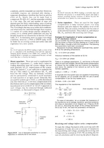
transmission level of 66 kV or 132 kV. Capacitors at
Z
such voltages may be connected through dedicated z=Px v," (from equation (13.3))
transformers, as illustrated in Figure 24.24. 100 kVAx lo3
- 10
66 or 132 kV line _- 33' x 106
100 ~ O X
lo6
= 3.63 R
For ease of calculation, let us consider the impedance of
Dedicated the transformer as its leakage reactance, ignoring resistance
transformer and draw an equivalent circuit diagram as in Figures 24.25
(b) and (c). Assuming the length of the primary distribution
I
line to be 15 km, the total line parameters will become
Switching XL = 3.63 + 15 x 0.4 + 3.63
= 13.26
and R = 0.13 x 15
banks
= 1.95 R
Receiving-end voltage before series compensation
To study the voltage fluctuation at the receiving-end with
fluctuations of loads, let us do so in terms of variation in
the transmitting-end voltage, assuming the receiving-end
Figure 24.24 Use of dedicated transformer to connect voltage remains constant at 33 kV. We are doing this for
capacitors on networks 66 kV and above ease of calculation and for drawing the phasor diagram.