
Page 848 - Industrial Power Engineering and Applications Handbook
P. 848
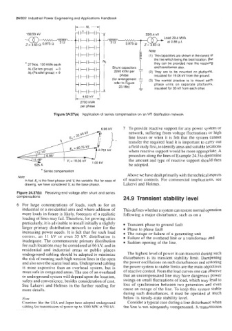
24/802  Industrial Power Engineering and Applications Handbook


             132/33 kV
                                                                         Load 29.4 MVA
                                                                          at 0.88 p.f.


                                                                  (1)  The capacitors are shown in the centre of
                                                                    the line which being the best location. But
            * 27 Nos. 100 kVAr each               Shunt capacitors   they  can be provided near the  receiving
                                                                     end transformer also.
             N,  (Series group)  = 3   HH          2240 kVAr per
             N2 (Parallel group) = 9                  phase       (2) They  are  to  be  mounted on  platforms,
                                                                     insulated for  19.05 kV from the ground.
                                    HH            (for arrangement   (3) The  normal practice  is  to  mount  each
                                                   refer to Figure   phase  units  on  separate  platforms,
                                    HH               23.18b)         insulated for 33 kV from each other.
                                    HH
        h)
                                    2700 kVAr
                                    per phase
                         Figure 24.27(a)
                                     Application of  series compensation on an HT distribution network
                                                       7  To provide reactive support for any power system or
                                             6.96 kv
                                                         network, suffering from voltage fluctuations or high
                                                                                           carry
                                                                         load
                                                                             it
                                                                                         to
                                                                                 important
                                                                                               out
                                                         transfer
                                                                   required
                                                                the
                                                         a field study first, to identify areas and suitable locations
                                 = 20.75 kv              line  losses  or  when   it  is  felt  is  that  the  system  cannot
                                            2.761 kV     where reactive support would be more appropriate. A
                 17.16"
                     6.95"                               procedure along the lines of Example 24.3 to determine
                11.48"        V, = 19.05 kV   ,oo kV     the amount and type of reactive support should then
                525 A                                    be adopted.
                   * Series compensation
         Note                                            Above we have dealt primarily with the technical aspects
            In fact E, is the fixed phasor and V, the variable  But for ease of   of reactive  controls. For commercial implications,  see
            drawing, we have considered V, as the base phasor.   Lakervi and Holmes.
        Figure 24.27(b)   Receiving-end voltage after shunt and series
        comDensations
                                                       24.9  Transient stability level
        6  For  large  concentrations  of  loads,  such  as  for  an
           industrial or a residential area and where addition of   This defines whether a system can restore normal operation
           more loads in future is likely, forecasts of a realistic   following a major disturbance, such as on a
           loading of lines may fail. Therefore, for growing cities
           particularly, it is advisable to install initially a slightly   Transient phase to ground fault
           larger  primary  distribution  network  to cater for the   Phase to phase fault
           increasing power needs. It is felt that for such load   The outage or failure of a generating unit
           centres,  an  11 kV  or  even  33  kV.  distribution  is   Failure of the overhead line or a transformer and
           inadequate. The commensurate primary  distribution   Sudden opening of the line.
           for such locations may be considered at 66 kV, and in
           residential  and  industrial  areas  or  public  places
           underground cabling should be adopted to rninimizc   The highest level of power it can transmit during such
           the risk of running such high tension lines in the open   disturbances is its transient  stability limit.  Dampening
           and also save the scarce load area. Underground cabling   the power oscillations on such disturbances and restoring
           is  more expensive than  an overhead system, but  is   the power system to stable limits are the main objectives
           more safe in congested areas. The use of an overhead   of reactive control. From the load curves one can observe
           or underground system will depend upon the location,   that an uncompensated line may have dangerous power
           safety and convenience, besides consideration of cost.   swings on small fluctuations of load, which may lead to
           See Lakervi  and Holmes  in  the further reading  for   loss of  synchronism between  two generators  and even
           more details.                               cause an outage of  the line. To keep this system stable
                                                       during such disturbances,  it must be operated at much
           Note                                        below its steady-state stability level.
           Countries like the USA and Japan have adopted underground   Consider a typical case during a line disturbance when
           cabling for transmission of  power up to  1000 MW at 550 kV.   the line is not adequately compensated. A transmission