
Page 844 - Industrial Power Engineering and Applications Handbook
P. 844
24/798 Industrial Power Engineering and Applications Handbook
its natural loading within stable limits and hence fulfil
or P,,, = Po x the requirement of economical power transfer. The above
was a theoretical analysis which can provide quite accurate
results, depending upon the accuracy of the data assumed.
Since there is no change in the shunt capacitance (X; = Xc ), The more scientific procedure to conduct this type of
= Po x -\I- study, however, would be through a load flow analysis of
7
11
:. P,,, = 2 Po
0.25 the steady-state component to study temporary
overvoltages and transient analysis through a TNA
While it is possible that PmaX may be further raised by a still
closer compensation, this is not advisable to retain the stability (transient network analyser) or an EMTP (electromagnetic
level of the system. The above compensation is even higher transient programme). TNA is an analogue method while
than the line length compensation considered earlier and will EMTP is a digital method of system analysis. For details
further improve the electrical line length. of system models and procedure to study a system, refer
Adding shunt capacitors would also reduce Z, but would to Miller (1982).
raise the electrical line length; hence it is not considered. A transmission line may have to operate under different
Moreover, on EHVs, the charging shunt capacitances, C,, as conditions of loading (I, and p.f.) at different hours of
such require compensation during light loads or load rejections
to limitthevoltage rise (regulation) atthe farendorthemidpoint. the day, and then there may also be seasonal loads. The
Hence no additional shunt compensation is recommended. type of reactive compensation therefore must be decided
for the varying load conditions, so that they are able to
Note provide a continuous change in the VAr as demanded. It
Series compensation would mean a low value of Z, and is normal practice to have a combination of series and
hence a higher system fault level. This needs be kept in mind shunt reactive compensations to suit all conditions of
while designing the system and selecting the switching devices loading, some fixed (unswitched) compensators for normal
or deciding on the protective scheme or its fault setting. load conditions and the remainder variable, to switch
ON or OFF depending upon the load conditions or load
Symmetrical lines fluctuations. The choice of different types of reactive
compensators may be considered on the following basis:
Equation (24.12) is now modified to
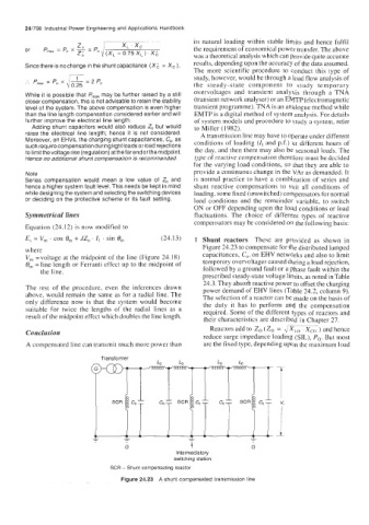
E, = V, . COS 0, + JZ, . I, . sin 0, (24.13) 1 Shunt reactors These are provided as shown in
where Figure 24.23 to compensate for the distributed lumped
V, =voltage at the midpoint of the line (Figure 24.18) capacitances, C,, on EHV networks and also to limit
0, = line length or Ferranti effect up to the midpoint of temporary overvoltages caused during a load rejection,
the line. followed by a ground fault or a phase fault within the
prescribed steady-state voltage limits, as noted in Table
24.3. They absorb reactive power to offset the charging
The rest of the procedure, even the inferences drawn power demand of EHV lines (Table 24.2, column 9).
above, would remain the same as for a radial line. The The selection of a reactor can be made on the basis of
only difference now is that the system would become the duty it has to perform and the Compensation
suitable for twice the lengths of the radial lines as a required. Some of the different types of reactors and
result of the midpoint effect which doubles the line length. their characteristics are described in Chapter 27.
Reactors add to Z, (Z, = JX,, Xco ) and hence
Conclusion
reduce surge impedance loading (SIL), Po. But most
A compensated line can transmit much more power than are the fixed type, depending upon the maximum load
G t G
Intermediatory
switching station
SCR - Shunt compensating reactor
Figure 24.23 A shunt compensated transmission line