
Page 839 - Industrial Power Engineering and Applications Handbook
P. 839
System voltage regulation 24i793
Under such a condition, the line will maintain a unity
p.f. at all points of the line and the reactive power
generated, due to the distributed line charging capacitances
(Co), is offset by the reactive power absorbed by the
distributed line inductances (Lo). The generator is now = 45 Zo (Zo is termed the natural or
=
not unduly stressed by the reactive power feedback, i.e.
surge impedance of the line)
"Z
-- -I; .XL0 The voltage will now maintain a flat profile from the
xco transmitting end through the receiving end and all the
where reactive power generated = V~/Xco per phase per insulators or terminal equipment would be equally stressed.
unit length and reactive power compensated (absorbed) If Vo is considered as the nominal phase voltage of the
= Zi . XLo per phase per unit length. Io is the capacitive system then equation (24.3) can be rewritten as
charging current
vc?
or %=,/- P = -. per phase (24.9)
Zo sin 8
IO
The concept behind the above equation is that the voltages
and the currents, at the transmitting and receiving ends
4 are maintained at the same p.f. The voltage at the receiving
end, however, will shift in phase with respect to the
voltage at the transmitting end by an angle 8, due to the
I
I Ferranti effect and that effect is considered in the above
I
I derivation. Refer to Figure 24.15 for more clarity. In the
I above equation the element V,/Zo is an important
I I I indicator of the power transfer capability of a line, and is
11.93; I / I I I I I I I (Po) of the line, i.e. (24.10)
termed the natural loading or surge impedance loading
vc?
P - - per phase
----
I I I O - zo
I Such a line is said to be naturally loaded and this
I assumption is true only when the power is being
I
I transmitted at unity p.f. and there is a total balancing of
I
I reactive powers. Since Zo is constant for an
I uncompensated line, so is Po, irrespective of its length.
I
I The magnitude of this will depend upon the line voltage,
I
I size of conductors and the spacings between them and
I from the ground (these parameters decide Co and LO and
I
I hence Zo). It is also an indicator of a normal loading
I
capacity of a line. The recommended practice is to load
15 30 45 60 75 90 an uncompensated line to near this value or a little above
Load
--- ang/e (6) --+ when the line is a little shorter, or a little less when the
line is longer to retain the level of stability. Also refer to
a radians the load curves in Figure 24.20 for more clarity.
To optimize this power transfer through reactive control
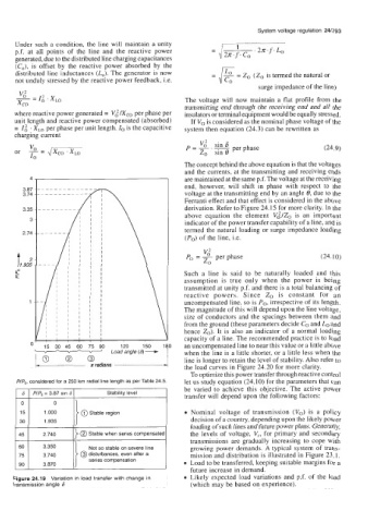
PIPo, considered for a 250 km radial line length as per Table 24.5. let us study equation (24.10) for the parameters that can
be varied to achieve this objective. The active power
Stability level transfer will depend upon the following factors:
@ Stable region Nominal voltage of transmission (Vo) .is a policy
30 1.935 decision of a country, depending upon the likely power
loading of such lines and future power plans. Generally,
F[ 2.740 1) @ Stable when series compensatedl the levels of voltage, V,, for primary and secondary
transmissions are gradually increasing to cope with
Not so stable on severe line growing power demands. A typical system of trans-
3.740 @ disturbances, even after a mission and distribution is illustrated in Figure 23.1.
series compensation Load to be transferred, keeping suitable margins for a
3.870
future increase in demand.
Figure 24.19 Variation in load transfer with change in Likely expected load variations and p.f. of the load
transmission angle 6 (which may be based on experience).