
Page 834 - Industrial Power Engineering and Applications Handbook
P. 834
241788 Industrial Power Engineering and Applications Handbook
90% generator Prime mover
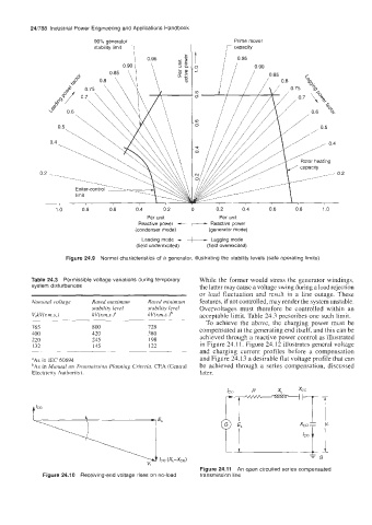
stability limit 7
t
I
0 I I 0.90
1 .o 0.8 0.6 0.4 0.2 0 0.2 0.4 0.6 0.8 1 .o
Per unit Per unit
Reactive power -+- Reactive power
(condenser mode) (generator mode)
Leading mode -+-- Lagging mode
(field underexcited) (field overexcited)
Figure 24.9 Normal characteristics of a generator, illustrating the stability levels (safe operating limits)
Table 24.3 Permissible voltage variations during temporary While the former would stress the generator windings,
system disturbances the latter may cause a voltage swing during a load rejection
or load fluctuation and result in a line outage. These
Nominal voltage Rated maximuni Rated minimum features, if not controlled, may render the system unstable.
stability level stabiliv level Overvoltages must therefore be controlled within an
V&V(r.m.s.) kV(r.m.s.)" kV(r.m.s. Jb acceptable limit. Table 24.3 prcscribes one such limit.
.~ ~~ ____~ To achieve the above, the charging power must be
765 800 728 compensated at the generating end itself, and this can be
400 420 380 achieved through a reactive power control as illustrated
220 245 198
132 145 122 in Figure 24.11. Figure 24.12 illustratcs general voltage
and charging current profiles before a compensation
"As in IEC 60694 and Figure 24.13 a desirable flat voltage profile that can
'As in Manual on Trunsnzission Planning Criteria, CEA (Central be achieved through a series compensation, discussed
Electricity Authority). later.
WXb
xcoi 11
4 'co f
v,
l l IC0 t I I
Figure 24.11 An open circuited series compensated
Figure 24.1 0 Receiving-end voltage rises on no-load transmission line