
Page 829 - Industrial Power Engineering and Applications Handbook
P. 829
241784 Industrial Power Engineering and Applications Handbook
Line length -
Sending Receiving
\ end end
-\
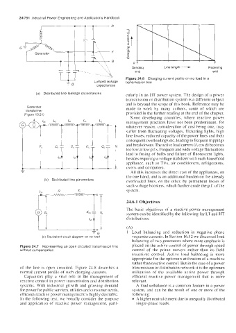
Figure 24.8 Charging current profile on no load in a
Lumped leakage transmission line
-G CaDacitances
(a) Distributed line leakage capacitances cularly in an HT power system. The design of a power
transmission or distribution system is a different subject
and is beyond the scope of this book. Reference may be
Generator
transformer made to work by many authors, some of which are
(Figure 13.21) provided in the further reading at the end of the chapter.
Some developing countries, where reactive power
management practices have not been predominant, for
whatever reason, consideration of cost being one, may
suffer froin fluctuating voltages, flickering lights, high
line losses, reduced capacity of the power Lines and their
consequent overloadings etc, leading to frequent trippings
and breakdowns. The active load current (I, cos 4) becomes
too low at low p.f.s. Frequent and wide voltage fluctuations
lead to fusing of bulbs and failure of fluorescent lights,
besides requiring a voltage stabilizer with each household
appliance. such as TVs, air conditioners, refrigerators,
ovens and computers.
All this increases the direct cost of the appliances, on
the one hand, and is an additional burden on the already
(b) Distributed line parameters overloaded lines, on the other, by permanent losses of
such voltage boosters, which further erode the p.f. of the
s y s tein .
24.6.1 Objectives
The basic objectives of a reactive power management
system can be identified by the following for LT and HT
distributions:
UG
(A)
1-
1 Load balancing and reduction in negative phase
(c) Equivalent circuit diagram on no load sequence currents. In Section 16.12 we discussed load
balancing of two generators where more emphasis is
Figure 24.7 Representing an open circuited transmission line placed on the active control of power through speed
without compensation control of the prime movers rather than its field
(reactive) control. Active load balancing is morc
appropriate for the optimum utilization of a machine
rather than reactive control. But in the case of a power
of the line is open circuited. Figure 24.8 describes a transmission or distribution network it is the optimum
normal current profile of such charging currents. utilization of the available active power through
Capacitors play a vital role in the management of efficient reactive power management that is more
reactive control in power transmission and distribution relevant.
systems. With industrial growth and growing demand A load unbalance is a common feature in a power
for power for public services, utilities and consumer needs, system, and can be the result of one or more of the
efficient reactive power management is highly desirable. following:
In the following text, we broadly consider the purpose A higher neutral current due to unequally distributed
and applicatioii of reactive power management, parti- single-phase loads.