
Page 832 - Industrial Power Engineering and Applications Handbook
P. 832
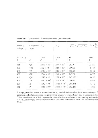
Table 24.2  Typical basic line characteristics (approximate)

                                                                                                             ~
                                                                             I, (It Pi,   Clia r,q ing  ‘  Churgitzg   ~  Ferrtrnti e8ec.t per km
                                                                                                      - -5
                                                                              --
                                                                              -
                                                                                                         0
                                                                                17 Zn                  x<
                               LZkm      ~  Wkrn    I2             MW        Amp        Atrip                ~  in rcrdintI.v   In degree5
                               3         !4         5              6          7         8            9       ~  10         11
                                          ~____~ ~-                     -
                                         ,                         ~                     ~       ~                  ~~~~
                                                                                                     ~
                                                    252.8          2315 0     1,747     I81          2.40    ~  1.036 x  IO-’   59 33 x  10-3
                                                    309.22          SI7 4      747      0 80         0.56     1.074 x  lo-’   61 51 x  IO ’
                               3.304 x  IO-’   2.82 x  10’   305.24   524 2    757      0 82         0.567    1.082 x 1 of   61 97 x  IO-’
                               2.544 x  IO-’  1  2.40 x  10’   247.09   647 5   935     0 96         0.67     I .03 x I 0-1   58.99 x 10
                                                                    645 6      932      IO1          0.70     I .082 x 10-3   61 97 x  IO-’
                                                                    558 9      807      0 84         0.584    1.045 x  10-3   59 85 x 10
              220      2       3 992 x 10  I  1  3  408 x 10’   368 846   131 2   344   0 31         0.142    1082 xIO-’   61.97 x  10 ’
                                                                    48 0       210      0 22         0 051    1 063 x  10   60.88 x 10 ’
                                                                                __
                                                                   ~~                                       ~-     ~~     _____
              Tharging reactive  power  is proportional to  V,’  and diminishes sharply at  lower voltages.  Charging reactive  power  mut be  \uitably  offset  at the point  of  power generation  to protect the
              generator and other connected eauipment from excesive overvoltagcs due to capacitive  charging.
               This reveals that on  a 50 Hz system the pha\e displacement between  the sending and receiving end voltagca, due to electromaynctic propagation  through the lines, is of the order of 6” per
              100 km. Accordingly, an uncompensated line should be restricted to about 400 kin in length in radial lines and 800 km in symmetrical  lines to avoid an overvoltage at the receiving end (Table
              24.5)